Supporting beam structure for automobile air suspension

A technology of air suspension and support structure, which is applied to suspensions, vehicle parts, cantilevers mounted on pivots, etc. Large coefficient, the effect of reducing bending moment

Pending Publication Date: 2019-12-27
江苏鼎帅汽车科技有限公司
View PDF1 Cites 0 Cited by
  • Summary
  • Abstract
  • Description
  • Claims
  • Application Information

AI Technical Summary

Problems solved by technology

[0003] After years of actual use, it is found that this structure still has the following problems: On the one hand, although the strength and rigidity of the automobile air suspension of this structure have been improved, in order to make it have sufficient supporting strength and rigidity, the thickness of its body material is too thick ( Its thickness is generally 7-8mm), and the total weight of the finished beam after tailor welding is > 110kg. It can be seen that the total weight is heavy and cannot meet the actual requirements of lightweight, which creates a support stiffness, strength requirements and light weight. The contradictory points of quantitative requirements, so even after years of technological development, there is still no way to come up with a good solution. According to data, in recent years, several domestic manufacturers have tried to use 6mm high-strength steel 610L or even ultra-high-strength steel. The high-strength steel 700L has been tested many times, and finally failed due to the sudden fracture of the fatigue strength within 100,000 times; Therefore, the material of the suspension beam must have good comprehensive properties such as strength, toughness, weldability, and cold forming; and because the intersection point (concentrated load) of the airbag center distance and eccentricity distance of the suspension beam of the air suspension beam varies according to different models, The concentrated load point also changes accordingly. In the current situation of more than ten years, nearly 90% of the airbag center distances and eccentric distances of the vehicle models are relatively small. For example, the above-mentioned published patents can no longer meet the general requirements. The included angles between the transition zone and the transition zone on both sides are small (45º and 49º). When the intersection of the two distances changes, the concentrated load has deviated to the edge of the beam, especially because the inner radius of the beam is small (10mm), and the outer layer Excessive tensile deformation of the material will cause the tensile stress to reach or exceed the tensile strength of the material and cause potential safety hazards of fracture; It belongs to the cantilever type beam and the concentrated load is at both ends. Its bending normal stress is distributed in a straight line, and the maximum value occurs on the upper and lower edges of the beam. The shear stress is distributed in a parabola, and the maximum value occurs on the central axis. Its bending resistance Strength is not guaranteed

Method used


Image

  • Supporting beam structure for automobile air suspension
  • Supporting beam structure for automobile air suspension
  • Supporting beam structure for automobile air suspension

Examples


Embodiment 1

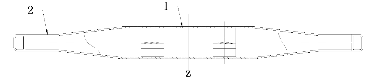
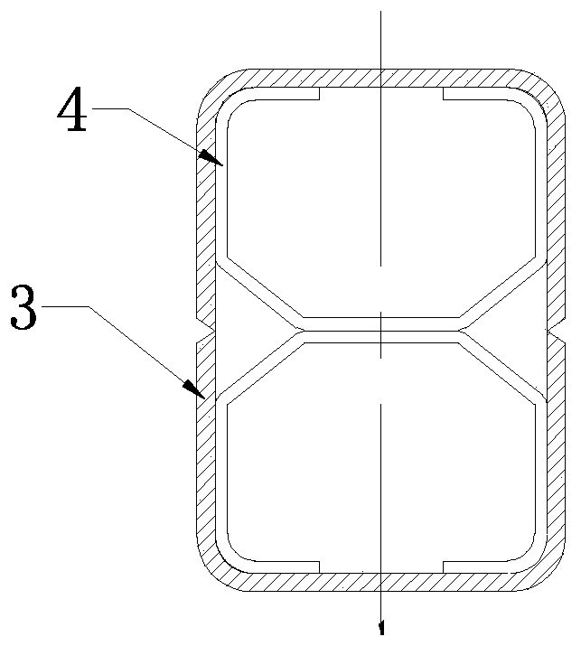
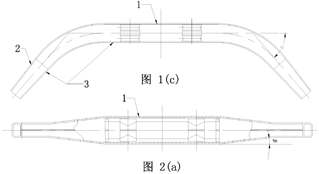
[0074] The support beam structure used for the automobile air suspension in this embodiment is actually a support beam with a split-type reinforced support structure inside the beam body, as shown in Figure 1(a)-Figure 1(c), wherein, In order to make the picture clearer, Figure 1(b) is enlarged at a ratio of 1:3, which includes the central axis section 1 of constant section and the variable section section 2 extending from both sides of the central axis section, the central axis section 1 and the variable section section 2. It has a through-integrated inner cavity, and the variable cross-section section is bent symmetrically along the radial centerline z of the central axis section to form a C-shaped beam structure. The variable section of the included angle forms a C-shaped beam structure. It can be seen from Figure 1 (a) that the C-shaped beam structure is a whole formed by welding the upper and lower halves of the profile, and the central axis section 1 is folded with the va...

Embodiment 2

[0077] The support beam structure used in the automobile air suspension in this embodiment is actually a support beam with a combined reinforced support structure inside the beam body, as shown in Figure 2(a)-Figure 2(c). The supporting frame 4 of the C-shaped structure used in the supporting beam structure of the automobile air suspension of the example is the same as that of the first embodiment, and the difference is that in this embodiment, it is also combined with the supporting frame 4 of the C-shaped structure. A U-shaped piece, that is to say, the support structure is composed of a set of upper support members and a set of lower support members. The upper support member consists of an upper U-shaped piece and an upper support placed in the upper U-shaped piece. The lower support member is composed of a lower U-shaped piece and a lower support frame placed in the lower U-shaped piece. At this time, the outer surface of the upper U-shaped piece is in full contact with the...

Embodiment 3

[0079] As shown in Figure 3(a)-Figure 3(b), in order to make the picture clear, Figure 3(b) has been enlarged at a ratio of 1:3, the support beam used for the air suspension of the automobile in this embodiment The structure is actually a support beam with the same support structure as that of Embodiment 2. It differs from Embodiment 2 only in that the shape of the support beam is different. In this embodiment, the inner surface of the central axis section of the C-shaped beam structure 3 Set as an arched curved surface structure, the middle part of the curved surface arched structure is a straight line segment, and the two sides of the straight line segment are connected with the body of the central axis segment through a curve, as shown in Figure 3 (b), the said inner side The surface refers to the surface where the variable cross-section section 2 extends. The inner side here is only equivalent to the opening direction of the C-shaped beam structure 3, and does not refer to ...


PUM


Abstract

The invention discloses a supporting beam structure for an automobile air suspension. The structure comprises a uniform cross-section middle shaft section and the variable cross-section sections extending from two sides of the middle shaft section, the variable cross-section sections are symmetrically bent along the radial center of the middle shaft section to form the C-shaped beam structures, and a supporting structure is arranged in an inner cavity of the middle shaft section and is provided with the surface supporting faces and the supporting tables. The two surface supporting faces at least make contact with the two opposite bearing force inner walls in the inner cavity of the middle shaft section respectively, and the supporting tables on the two surface supporting faces serve as theinternal supports of the two opposite bearing force inner walls. The device has the advantages that the ratio of the cross section factor to the cross section area is larger, so that the structure ismore reasonable, the bending resistance is stronger, and the structure is more reasonable and safer; the weight is lighter due to the adoption of a reasonable decrement structure, the strength, rigidity, inherent frequency and resonance phenomenon of the beam are ensured, the general requirements are met, but also the potential safety hazards of unbalance loading, breakage and rollover easily caused by different vehicle models are solved.

Description

technical field [0001] The invention relates to an automobile air suspension structure, in particular to a support beam structure used for the automobile air suspension. Background technique [0002] According to relevant research data, the car body accounts for about 30% of the total mass of the car. If the mass of the whole car is reduced by 10%, the fuel efficiency can be increased by 8% to 12%. Therefore, "lightweight" has become a key research topic in the development of the global automobile industry. Automobile air suspension is an important safety component that bears loads in automobiles, and its strength and stiffness requirements are very high. The existing automobile air suspension There are various structural forms, especially the patent No. 200720037500.8 proposed by the inventor in 2007, which is named as a utility model patent for suspension beams used in automobile air suspensions. The pieces are tailor-welded into a hollow rectangular beam, including the c...

Claims


Application Information

Patent Timeline
Patent Type & Authority Applications(China)
IPC IPC(8): B60G7/00
CPCB60G7/001
Inventor 帅启林
Owner 江苏鼎帅汽车科技有限公司
Why Eureka
Try Eureka