Integrated cooling device for hydraulic transmission locomotive

A cooling device and hydraulic transmission technology, applied in the direction of fluid pressure actuation device, engine components, engine lubrication, etc., can solve the problems of high cost, unsafe, complicated, etc., and achieve simple, orderly and simplified pipeline layout. The effect of cooling device arrangement and simplified design and production

Pending Publication Date:
View PDF2 Cites 0 Cited by
  • Summary
  • Abstract
  • Description
  • Claims
  • Application Information

AI Technical Summary

Problems solved by technology

[0003] However, in the process of implementing the embodiments of the present invention, the inventors of the present application have found that the above-mentioned technology has at least the following technical problems: on the one hand, according to the different types of heat source combinations that need to be cooled, the heat distribution ratio of the heat source is different, and according to the different driving methods of the locomotive cooling fan, Diesel engine cooling methods and power are different, as well as common cooling conditions. It is necessary to design a variety of cooling devices to achieve heat dissipation. The design cost is high and often cannot meet the heat dissipation requirements of different heat source combinations and different proportions of heat sources; another On the one hand, due to the many, complicated, and scattered pipelines of different heat sources entering and leaving the radiator, it is not safe, and if there is a heat dissipation problem in the cooling system, it is not easy to check for leaks for maintenance

Method used


Image

  • Integrated cooling device for hydraulic transmission locomotive
  • Integrated cooling device for hydraulic transmission locomotive
  • Integrated cooling device for hydraulic transmission locomotive

Examples


Embodiment 1

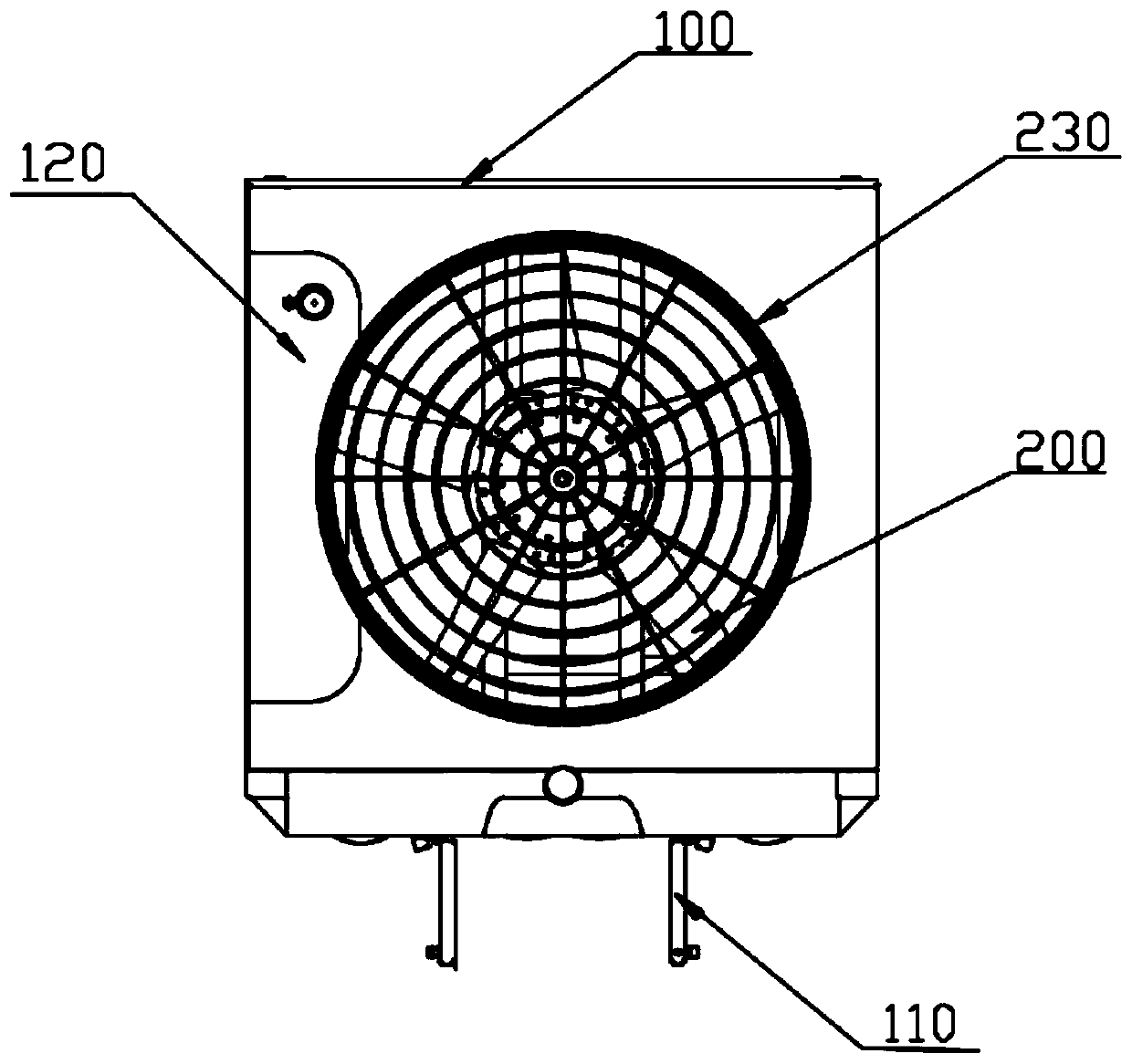
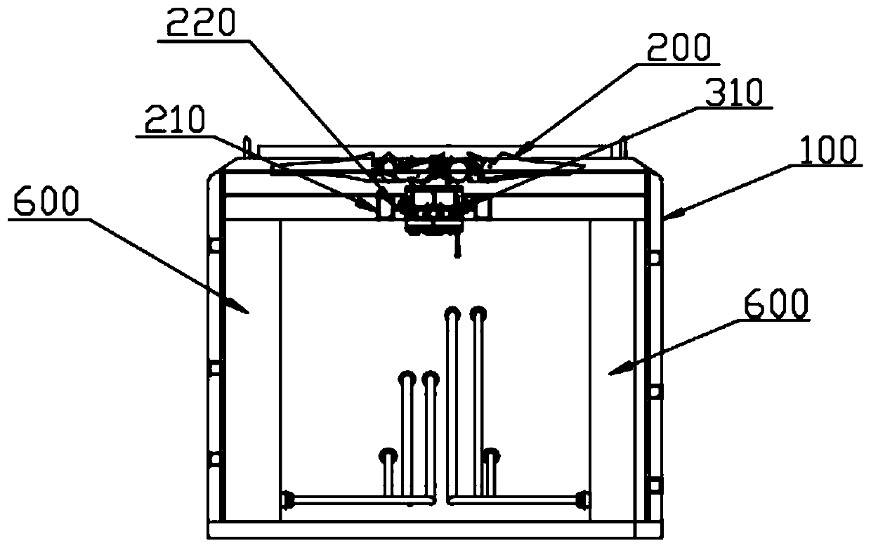
[0040] The embodiment is basically as figure 1 and figure 2 As shown: this embodiment provides an integrated cooling device for a hydraulic transmission locomotive, including a cooling housing 100, a cooling fan 200, and a fan mounting plate 220. One side of the cooling housing 100 has an inspection door 110, which can be accessed through the inspection door. The door 110 checks its internal cooling device; and on the top of the cooling shell 100, there is a storage room 120 for containing the expansion tank, which can effectively integrate the expansion into the cooling shell 100 to avoid additional storage space, and can ensure that the expansion tank is installed Requirements at heights. A mounting base 210 is fixedly installed on the upper middle of the cooling housing 100, and the mounting base 210 is fixed on the inner wall of the cooling housing 100 through a detachable connection with bolts; and a detachable fan mounting plate 220 is installed on the mounting base 21...

Embodiment 2

[0047] Embodiment 2 is basically the same as Embodiment 1, the difference is: please combine Figure 4 and Figure 6 As shown, this embodiment can provide a combination of four different heat sources for air, water, engine oil and transmission oil, specifically including air inlet and outlet, cooling water inlet and outlet, engine oil inlet and outlet, transmission oil inlet and outlet, and hydrostatic oil inlet and outlet ; Thereby blocking unnecessary hydrostatic oil inlet and outlet, correspondingly distributing the heat dissipation single section inside the cooling housing 100 into four radiators 600, the four radiators 600 are specifically cooling water radiators 620 and air radiators 610 , engine oil radiator 630 and transmission oil radiator 640, the inlet and outlet 400 of the four heat sources are respectively connected to the corresponding radiator 600 through pipelines, and a cooling device is realized through the ancient official road to meet the heat dissipation r...

Embodiment 3

[0049] Embodiment 3 is basically the same as Embodiment 1, the difference is: please refer to Figure 7 As shown, the drive mechanism 300 provided in this embodiment is a hydrostatic motor 320 as a power element, and the installation requirements for the hydrostatic motor 320 to drive the cooling fan 200 are met by adjusting the fan mounting plate 220, specifically, the hydrostatic pump of the hydrostatic motor 320 322 is fixed on the fan mounting plate 220 by fixing parts such as lock nuts, and the output shaft of the hydrostatic pump 322 is connected to the rotating shaft of the cooling fan 200 by transmission. The specific driving method and control principle of the fan driven by the hydrostatic motor 320 are prior art For example, Chinese Patent Publication No. CN203114404U discloses a forklift engine cooling system with a hydrostatically driven fan, and the cooling fan 200 is driven by a hydrostatic motor 320 . However, in this embodiment, the detachable connection betwee...


PUM


Abstract

The invention discloses an integrated cooling device for a hydraulic transmission locomotive and relates to the technical field of hydraulic transmission shunting cooling equipment. The integrated cooling device for the hydraulic transmission locomotive comprises a cooling shell, a cooling fan and a fan installing plate. A port connected with the cooling fan is formed in the upper end of the fan installing plate. A driving mechanism providing power for the cooling fan is installed at the lower end of the fan installing plate. Multiple heat source inlets and outlets are formed in the other side, relative to a maintenance door, of the cooling shell, and radiators corresponding to the heat source inlets and outlets are arranged on side walls of two sides of the cooling shell. The heat sourceinlets and outlets communicate with the radiators corresponding to the heat resource inlets and outlets respectively through pipelines. By implementing the technical scheme of the integrated cooling device for the hydraulic transmission locomotive, the technical problem that multiple kinds of cooling devices need to be designed to achieve heat dissipation for an existing hydraulic transmission locomotive can be effectively solved; and it can be achieved that heat dissipation requirements for different heat source combination and different heat source heat allocation proportion are met by one cooling device. The cooling device is highly integrated and good in safety and has better heat dissipation effect.

Description

technical field [0001] The invention relates to the technical field of hydraulic transmission shunting cooling equipment, in particular to an integrated cooling device for hydraulic transmission locomotives. Background technique [0002] In recent years, with the vigorous development of my country's rail transit, rail subway hydraulic transmission shunting locomotives have a broad application market. The locomotive cooling system is an important part of the hydraulic transmission shunting. The main heat sources that need to be cooled by the hydraulic transmission shunting include transmission oil, engine oil, air, water, and hydrostatic oil. Generally, the existing locomotive cooling system consists of various cooling devices. The cooling device includes a cooling fan and a driving mechanism for driving it to rotate, and a radiator. Commonly used drive methods for existing cooling fans mainly include: hydrostatic drive, motor drive, and coupler drive. [0003] However, in ...

Claims


Application Information

Patent Timeline
Patent Type & Authority Applications(China)
IPC IPC(8): F15B21/0423F16N39/02
CPCF15B21/0423F16N39/02Y02T30/00
Inventor 李连凯宋建林隆孝军钱纪富蔡小波胡利航
Why Eureka
Try Eureka