Device for hydro-mechanical characteristic test sampling and harmful gas cutting efficiency test
A technology for characteristic testing and harmful gas, which is applied in the preparation of test samples, soil material testing, material inspection products, etc. Problems such as parameter error estimation, etc., to achieve the effect of simple operation, easy production of materials, simple sample preparation method and production process
- Summary
- Abstract
- Description
- Claims
- Application Information
AI Technical Summary
Problems solved by technology
Method used
Image
Examples
Embodiment 1
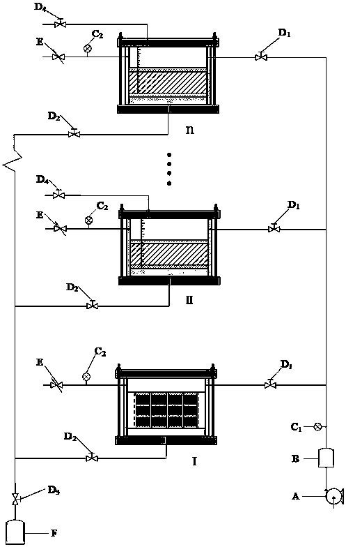
[0033] see Figure 1~Figure 9 , the water-mechanical characteristic test sample preparation and harmful gas reduction efficiency test device, including compressed air source A, gas storage tank B, gas flow meter C, stop valve D, safety valve E and simulated gas source F, is characterized in that: The compressed air source A passes through the gas storage tank B and the gas flow meter A C 1 Parallel through several cut-off valves A D 1 Connect 6 function one test chambers I and n-1 function two test chambers II-n; the bottom of the function one test room I and n-1 function two test chambers II-n have ports through n stop valves respectively B D 2 After parallel connection, pass through a stop valve C D 3 Connect the simulated gas source F, and their left sides respectively have ports through a gas flow meter BC 2 Connected to a safety valve E, the tops of n-1 function two test chambers II-n are respectively connected to a shut-off valve D 4 .
Embodiment 2
[0035] This embodiment is basically the same as Embodiment 1, and the special features are as follows:
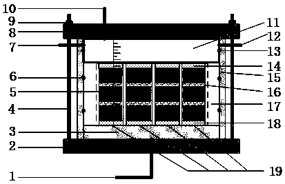
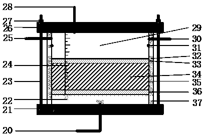
[0036]The first function test room and the second function test room are composed of an outer support, a base, a function first test room and a second function test room, and an air cavity. The outer support includes circular aluminum alloy bottom plates 2 and 21, threaded screw rods 4 and 23, annular aluminum alloy top plates 8 and 26 and nuts 9 and 27; the circular aluminum alloy bottom plates 2 and 21, annular aluminum alloy top plates 8 and 26, four bolt holes are respectively arranged around it, and the bolt holes of the base plate and the top plate correspond one by one; the screw rods 4 and 23 are full-thread screw rods, and are fixed in the screw holes of the circular aluminum alloy base plates 2 and 21, By changing nuts 9 and 27, adjust the height of the annular top plate.
[0037] The base includes bases 3 and 22 with spiral grooves on the bottom and side walls 1...
experiment example 1
[0043] Carry out water-mechanical characteristics timeliness test preparation test, enable figure 1 Part I of the structure diagram.
[0044] Step 1: Place the bottom plate 2 on the workbench, place the base 3 with a concave groove on the bottom plate 2, install the four threaded screw rods 4 on the screw holes 38 respectively, and place the lower permeable stone 18 on the base 3 to ensure The permeable stone is just embedded in the concave groove of the base.
[0045] Step 2: After the lower permeable stone 18 is installed on the base, place an acrylic plastic side wall 15 above it, and then install a sample chamber 17 with several small sample cylinders 19 in the side wall 15. O-rings 6 are installed at the upper and lower parts to ensure the sealing between the side wall 15 and the sample chamber 17 . A scale 5 is installed on the side wall of the sample cylinder 17, which can be used to observe the variation of the sample height.
[0046] Step 3: apply sealing silicone ...
PUM
 Abstract
Description
Claims
Application Information
 - R&D
- Intellectual Property
- Life Sciences
- Materials
- Tech Scout
- Unparalleled Data Quality
- Higher Quality Content
- 60% Fewer Hallucinations
Browse by: Latest US Patents, China's latest patents, Technical Efficacy Thesaurus, Application Domain, Technology Topic, Popular Technical Reports.
© 2025 PatSnap. All rights reserved.Legal|Privacy policy|Modern Slavery Act Transparency Statement|Sitemap|About US| Contact US: help@patsnap.com


