Positioning system based on distributed optical resonance system

An optical resonance, positioning system technology, applied in radio wave measurement systems, using re-radiation, measuring devices, etc., can solve the problems of complex operation, difficult aiming, resonance interruption, etc., achieve high-precision target position estimation, and achieve target position. estimated effect

Active Publication Date: 2019-12-27
TONGJI UNIV
View PDF8 Cites 0 Cited by
  • Summary
  • Abstract
  • Description
  • Claims
  • Application Information

AI Technical Summary

Problems solved by technology

However, the distributed optical resonance system with a single cavity structure requires the beam in the cavity to achieve propagation (LOS). If the beam is blocked by any object, the resonance will be interrupted.
Therefore, there is a need for a positioning system that can solve targeting difficulties, complex operations and meet safety constraints

Method used


Image

  • Positioning system based on distributed optical resonance system
  • Positioning system based on distributed optical resonance system
  • Positioning system based on distributed optical resonance system

Examples


Embodiment 1

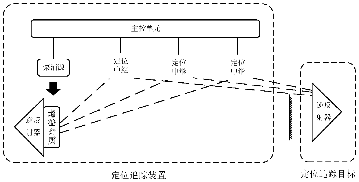
[0047] Example of three-point positioning:

[0048] Such as image 3 As shown, a more specific positioning implementation is given. Here, the three-dimensional space position of the point to be detected is determined according to the direction information returned by the three reference points. The positioning relay node is a direction-aware repeater, which can be refined into a CCD array and a relay reflection element.

[0049] In this embodiment, the direction-aware relay can measure the direction information of the positioning target. According to the principle of three-point positioning, the three directions of the positioning target determined by the three-direction sensing repeater, thereby determining the three-dimensional position information of the positioning target. The CCD array in the direction sensor uses the transverse photoelectric effect to detect the photoelectric position and coordinate information, and provides high linearity two-dimensional relative pos...

Embodiment 2

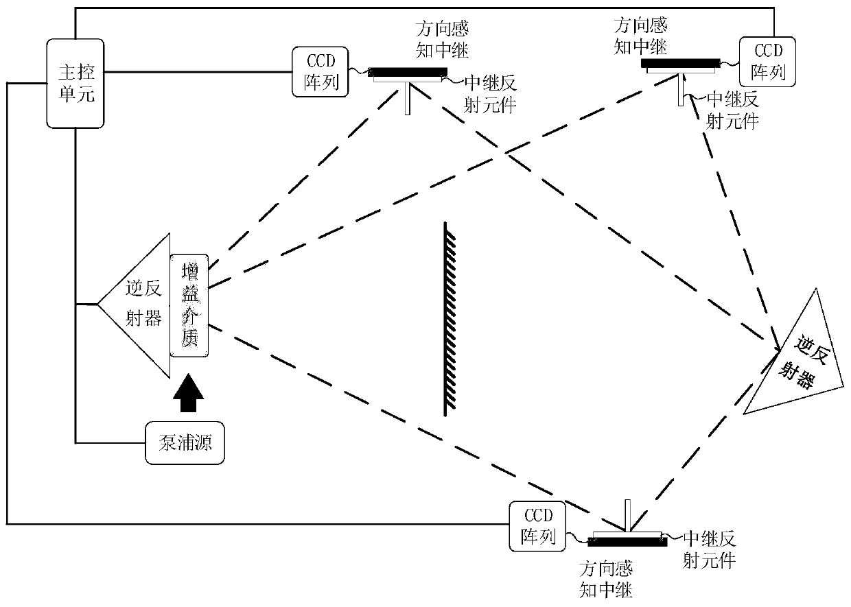
[0054] Example of three-point positioning of plane mirror relay:

[0055] Figure 4 An embodiment of three-point positioning using plane mirror relay is illustrated. Here, the three-dimensional space position of the point to be detected is determined according to the direction information returned by the three reference points. The positioning relay node is a direction-aware repeater, which can be refined into a CCD array and a relay reflection element.

[0056] In this embodiment, the direction-aware relay can measure the direction information of the positioning target. According to the principle of three-point positioning, the three directions of the positioning target determined by the three-direction sensing repeater, thereby determining the three-dimensional position information of the positioning target. The CCD array in the direction sensor uses the transverse photoelectric effect to detect the photoelectric position and coordinate information, and provides high line...

Embodiment 3

[0060] Example of three-point distance positioning:

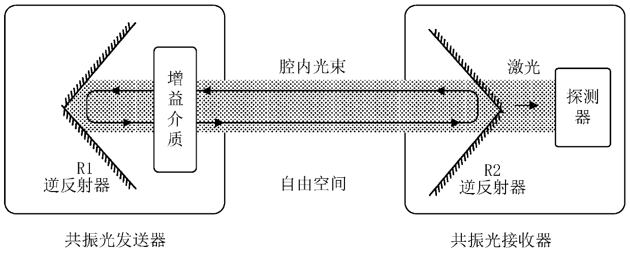
[0061] Figure 5 A three-point positioning embodiment using an interferometric range finder is illustrated. In this embodiment, the structure of the first retro-reflector, the pump source, the relay reflection element, the gain medium and the second retro-reflector is consistent with the working principle of the first embodiment. However, in this embodiment, the distance measuring unit is used to determine the three-dimensional space position of the point to be detected according to the distance information returned by the three reference points. The positioning relay node is a ranging relay, which can be refined into a relay reflection element, an interference ranging unit, an interference beam splitter, and a total reflection unit.

[0062] The interferometric ranging unit includes a Michelson interferometric ranging module and a spot ranging module. The Michelson interferometric ranging module provides high-precision ...


PUM


Abstract

The invention relates to a positioning system based on a distributed optical resonance system, and the positioning system comprises a positioning and tracking device provided with a first retroreflector and a gain medium, and a positioning and tracking target with a second retroreflector, wherein the positioning and tracking device further comprises at least one positioning relay node disposed between the first retroreflector and the second retroreflector, and a main control unit respectively communicating with the positioning relay nodes; a composite optical resonance cavity with a relay is formed among the first retroreflector, a plurality of positioning relay nodes and the second retroreflector; a back-and-forth oscillating composite cavity beam is formed in the composite optical resonance cavity, and the main control unit obtains part of the position information of the positioning and tracking target from the positioning relay nodes to confirm the spatial position of the positioning and tracking target. Compared with the prior art, the positioning system provided by the invention has the advantages such as high-precision positioning, movable positioning and tracking target andsight-unrestricted positioning.

Description

technical field [0001] The invention relates to the field of optical resonance wireless positioning, in particular to a positioning system based on a distributed optical resonance system. Background technique [0002] With the rapid development of the Internet of Things, the truly "connected" world of the Internet of Everything is getting closer and closer to reality. The Internet of Everything will eventually return to the connection between people and people, between things and people, and between people, and indoor positioning can quickly combine these connections. In recent years, indoor positioning has not only been widely used in airports, hospitals, large shopping malls, convention centers, and large parking lots, but also provides a data basis for services such as people flow guidance and personalized shopping in the era of big data. Existing indoor positioning mainly includes infrared positioning, Wi-Fi positioning, ultrasonic positioning, RFID positioning, UWB (ul...

Claims


Application Information

Patent Timeline
Patent Type & Authority Applications(China)
IPC IPC(8): G01S11/12
CPCG01S11/12
Inventor 徐梦圆刘明清刘庆文邓浩熊明亮
Owner TONGJI UNIV
Why Eureka
Try Eureka