Permanent magnet and method of making permanent magnet

A technology of magnets and magnetic moments, applied in the field of permanent magnets and manufacturing permanent magnets, can solve the problems of reduced coercive force of Nd-Fe-B magnets, etc.

Pending Publication Date: 2019-12-27
FORD GLOBAL TECH LLC
View PDF0 Cites 1 Cited by
  • Summary
  • Abstract
  • Description
  • Claims
  • Application Information

AI Technical Summary

Problems solved by technology

However, the coercivity of Nd-Fe-B magnets decreases with increasing temperature

Method used


Image

  • Permanent magnet and method of making permanent magnet
  • Permanent magnet and method of making permanent magnet
  • Permanent magnet and method of making permanent magnet

Examples


Embodiment Construction

[0012] Embodiments of the disclosure are described herein. It should be understood, however, that the disclosed embodiments are merely examples and that other embodiments may take various and alternative forms. The figures are not necessarily to scale; some features may be exaggerated or minimized to show details of particular components. Therefore, specific structural and functional details disclosed herein are not to be interpreted as limiting, but merely as a representative basis for teaching one skilled in the art to variously employ the embodiments. As will be understood by persons of ordinary skill in the art, various features shown and described with reference to any one of the figures may be combined with features shown in one or more other figures to produce the embodiment. Combinations of features shown provide representative embodiments for typical applications. However, various combinations and modifications of the features consistent with the teachings of this ...


PUM

PropertyMeasurementUnit
Curie pointaaaaaaaaaa

Abstract

The disclosure provides a permanent magnet and a method of making a permanent magnet. A method includes mixing first and second alloys to form a mixture, pressing the mixture within a first magnetic field to form a magnet having anisotropic particles of the first alloy aligned with a magnetic moment of the magnet, and heat treating the magnet within a second magnetic field to form elongated grainsfrom the second alloy and align the elongated grains with the moment.

Description

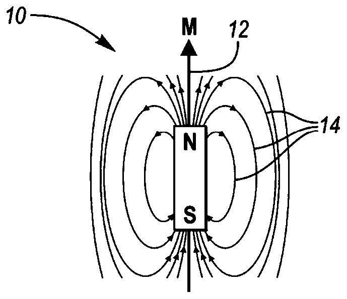
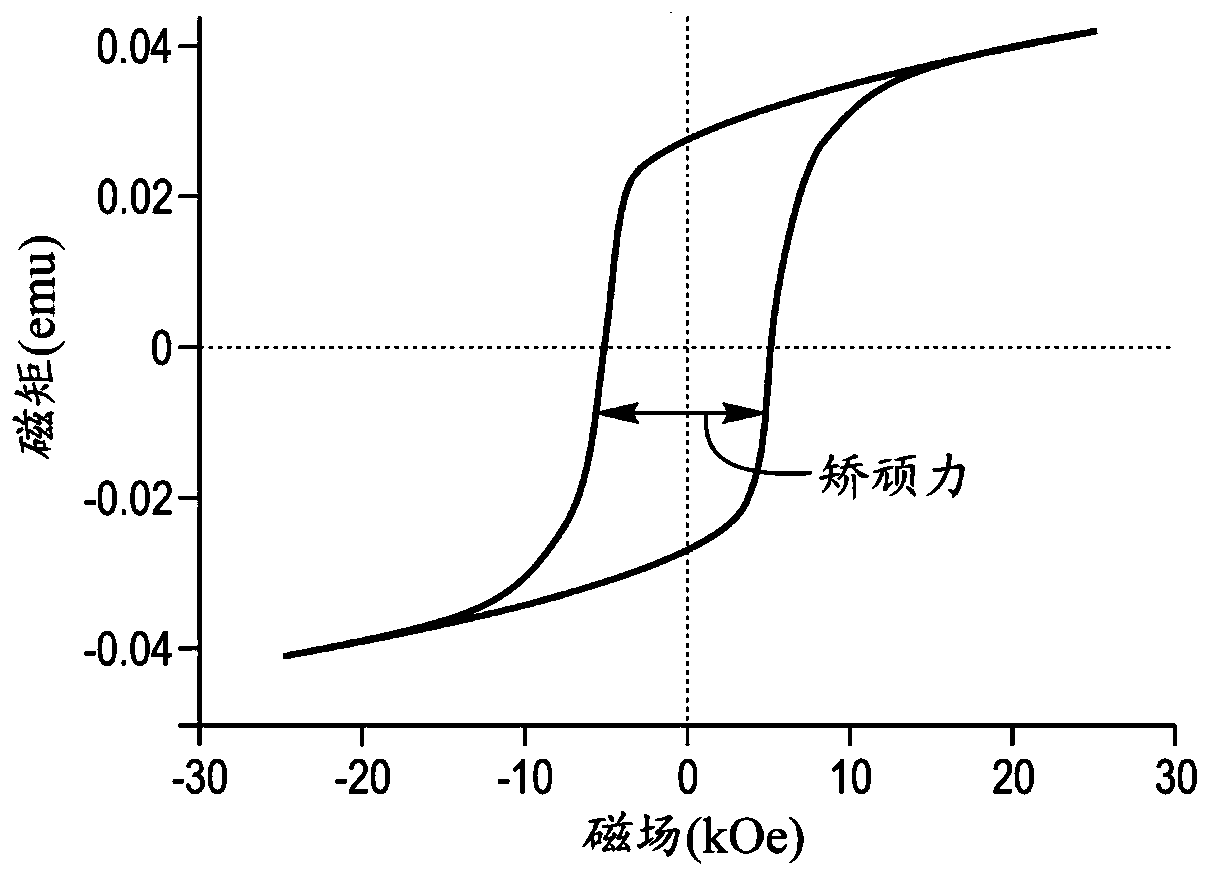
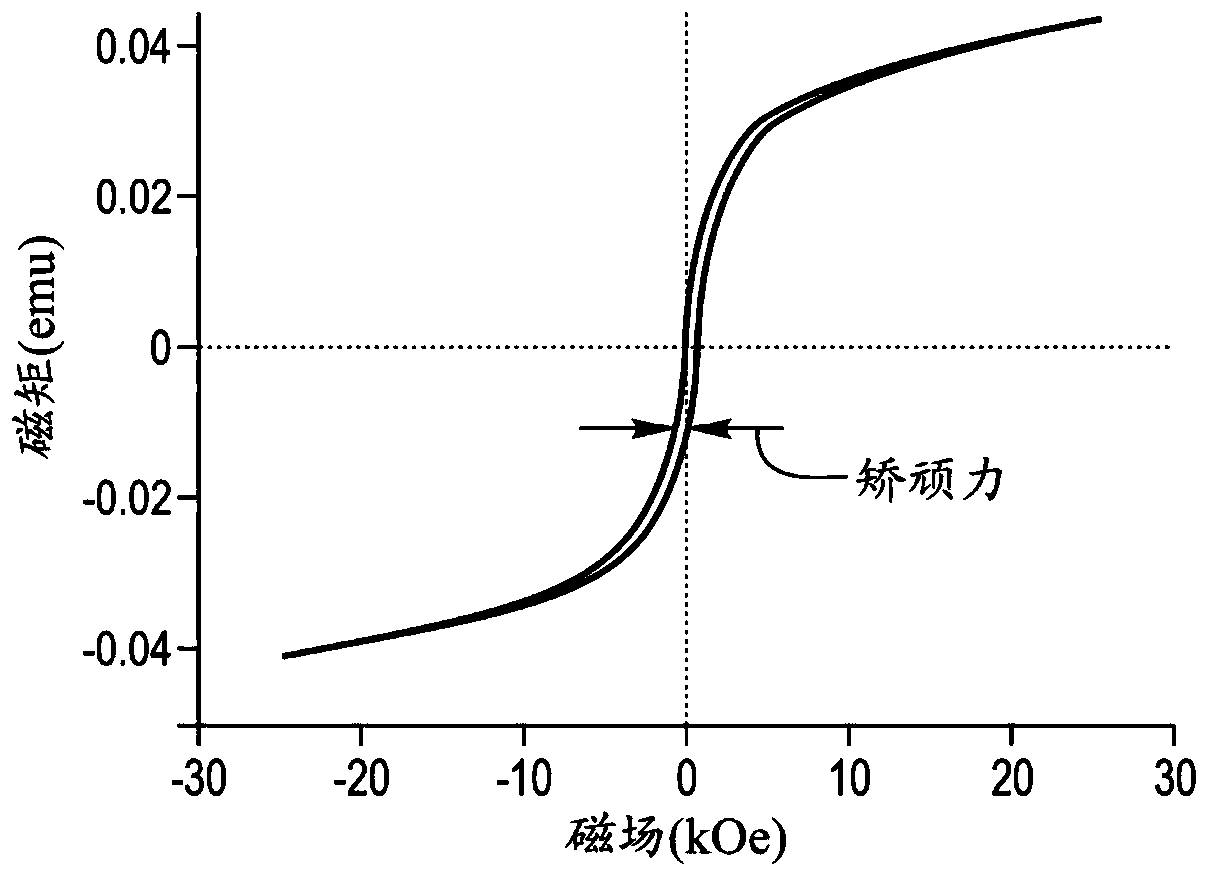
technical field [0001] The present disclosure relates to permanent magnets and methods of making permanent magnets. Background technique [0002] Neodymium iron boron (Nd-Fe-B) alloy magnets have been used in permanent magnet electrical machines such as motors, generators or motor / generator combinations. In order to meet the high temperature demands of operating permanent magnet electric machines, especially those used in electric and hybrid vehicles, the high temperature stability of the permanent magnets is required. However, the coercivity of Nd-Fe-B magnets decreases with increasing temperature. Coercivity is the ability of a magnet to withstand an external magnetic field without being demagnetized. Contents of the invention [0003] One method comprises: mixing a Mn-Bi alloy with Nd-Fe-B alloy powder having Nd-Fe-B anisotropic particles to form a mixture; compressing the mixture in a first magnetic field to form a magnet such that The Nd-Fe-B anisotropic particles ...

Claims


Application Information

Patent Timeline
Patent Type & Authority Applications(China)
IPC IPC(8): H01F41/02H01F7/02C22C1/04B22F1/00B22F3/02B22F3/24
CPCB22F1/0003B22F3/02B22F3/24B22F2003/248B22F2999/00C22C1/04H01F7/02H01F41/0273B22F2202/05C21D1/04C21D6/007H01F1/0576H01F1/08C30B30/04C30B33/04H01F1/0573H01F1/0577H01F41/0253
Inventor 李万锋梁峰迈克尔·W·德格纳
Owner FORD GLOBAL TECH LLC
Why Eureka
Try Eureka