A Rational Number Resonant Multi-Wavelength Coding Method Based on Dynamic Q-switching

A coding method and a rational number technology, applied in the field of ultrafast lasers and lasers, can solve the problems of lack of spectral energy density and peak power, not suitable for fast CARS imaging, etc., to achieve the effect of wavelength modulation and compact structure

Active Publication Date: 2021-08-31
CHONGQING INST OF EAST CHINA NORMAL UNIV +3
View PDF8 Cites 0 Cited by
  • Summary
  • Abstract
  • Description
  • Claims
  • Application Information

AI Technical Summary

Problems solved by technology

Although the supercontinuum meets the requirements of simultaneous CARS imaging of multiple substances, it lacks spectral energy density and peak power, and is not suitable for fast CARS imaging

Method used


Image

  • A Rational Number Resonant Multi-Wavelength Coding Method Based on Dynamic Q-switching
  • A Rational Number Resonant Multi-Wavelength Coding Method Based on Dynamic Q-switching
  • A Rational Number Resonant Multi-Wavelength Coding Method Based on Dynamic Q-switching

Examples


Embodiment 1

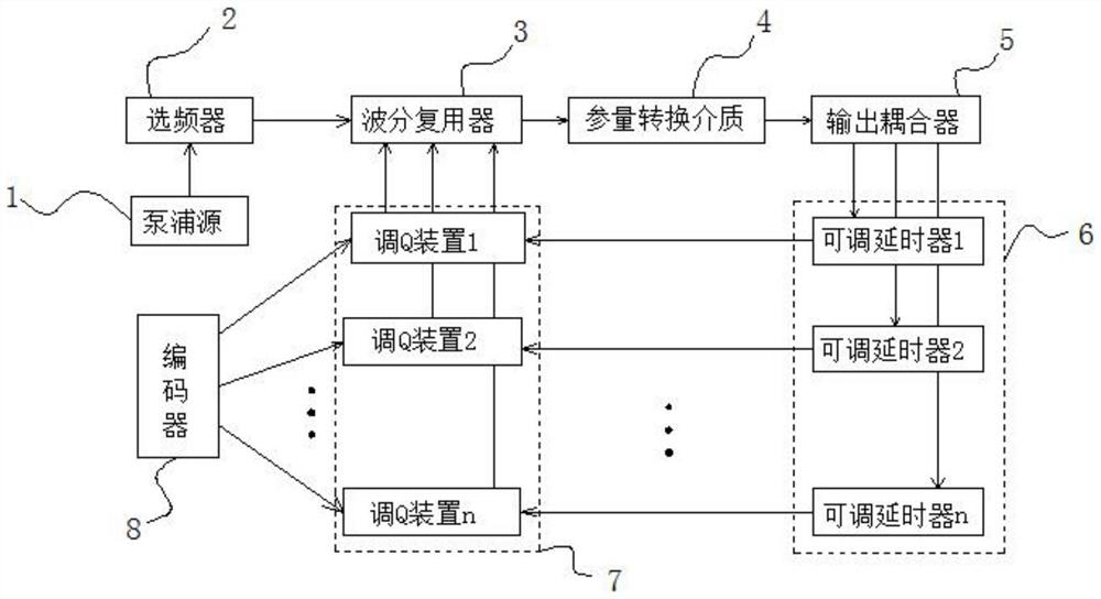
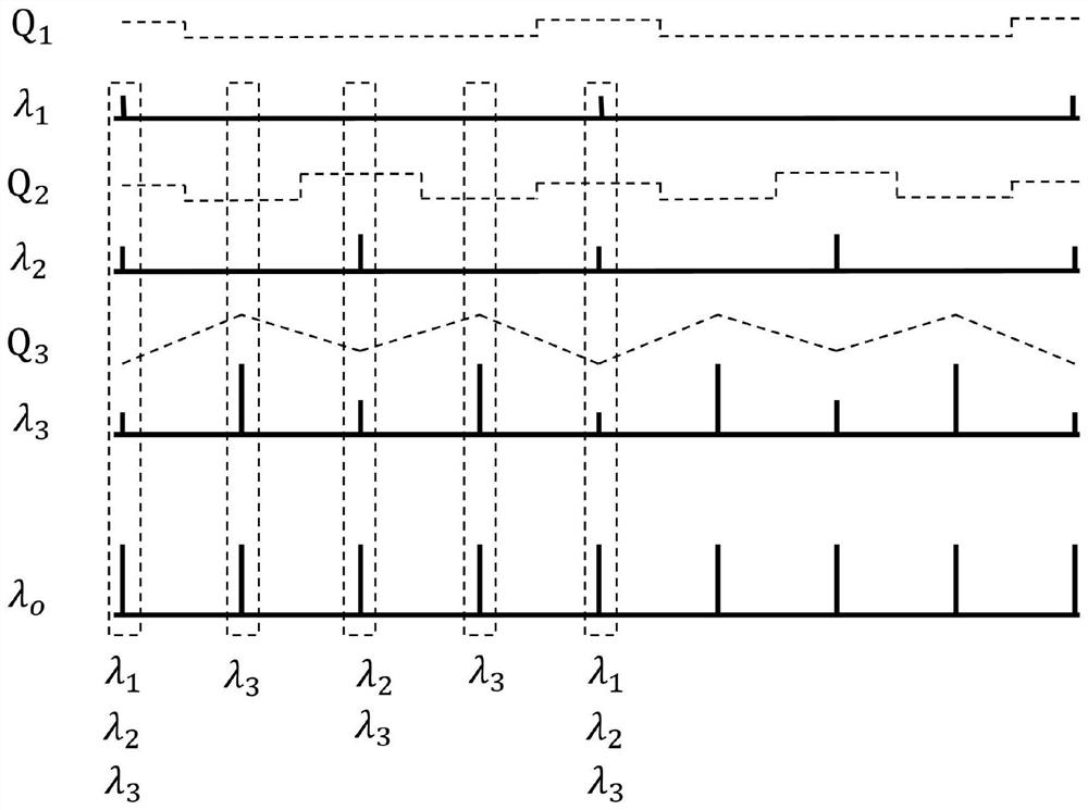
[0037] Such as figure 2 As shown, it includes three-way feedback, and the three Q-switching devices 7 are simultaneously controlled by the encoder 8, so that the Q values ​​in the three-way oscillation cavity are respectively as follows: figure 2 shown; in Q 1 , Q 2 , Q 3 λ under three kinds of Q value modulation 1 ,λ 2 ,λ 3 Resonant pulses such as figure 2 shown. lambda 1 ,λ 2 ,λ 3 Combination forms the output resonance pulse sequence λ of the present invention o . through as figure 2 The Q-value modulation shown so that λ 1 The repetition frequency is f, λ 2 With a repetition rate of 2f, λ 3 The repetition rate is 4f. lambda 1 ,λ 2 ,λ 3 The first pulses of the pulse train are synchronized in time and overlap in space to form λ o The first pulse, λ o The first pulse contains λ 1 , lambda 2 , lambda 3 Three wavelengths; it can be seen from the figure that λ o The second pulse contains only λ 3 a wavelength; λ o The third pulse contains λ 2 , lam...

Embodiment 2

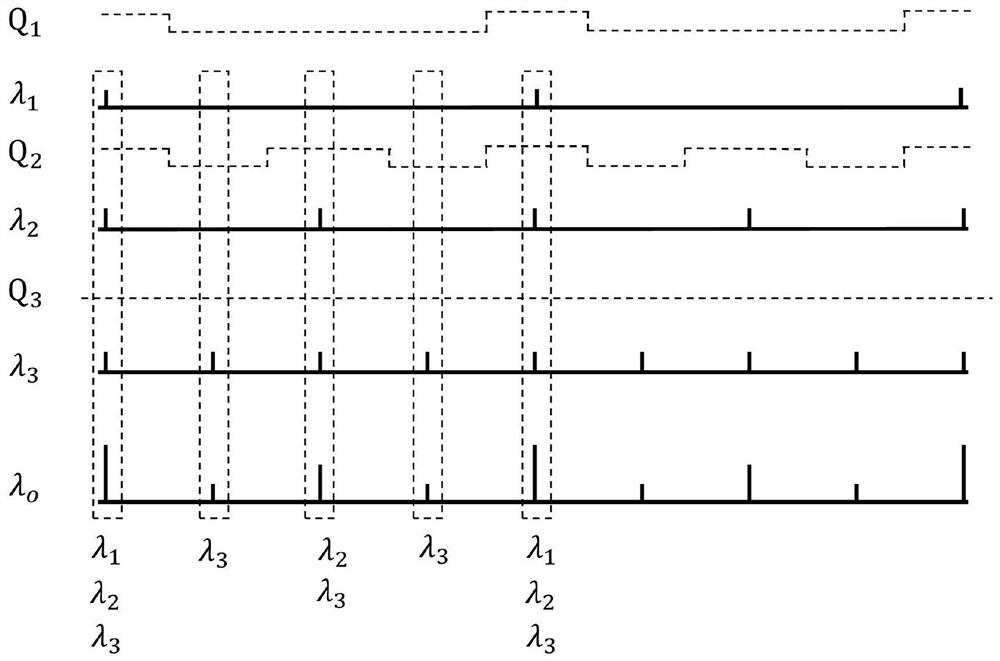
[0039] Such as image 3 As shown, the three Q-modulating devices 7 are controlled by the encoder 8 at the same time, so that the Q values ​​in the three-way oscillation cavity are respectively as follows: image 3 shown in Q 1 , Q2 , Q 3 λ under three kinds of Q value modulation 1 ,λ 2 ,λ 3 Resonant pulses such as image 3 shown. In the case of such Q-value coding, λ 1 ,λ 2 ,λ 3 The intensity of each pulse is dynamically modulated periodically, so that the output pulse λ o The pulse intensities are the same, the results are as follows image 3 shown.

[0040] figure 2 and image 3 Shown is the case of three-way feedback, in which case the output pulse λ o Contains at most λ 1 ,λ 2 ,λ 3 Three resonant wavelengths, plus the remaining pump light λ p , so the output pulse λ o A total of lambda p ,λ 1 ,λ 2 ,λ 3 Four wavelengths. According to CARS microscopic imaging conditions, two different wavelengths can image a substance, and there are the following six...


PUM


Abstract

The invention discloses a rational number resonant multi-wavelength encoding method of dynamic Q-switching, which includes sequentially connected pump sources, frequency selectors, 1*(n+1) wavelength division multiplexers, parameter conversion media, 1*( n+1) output coupler, n adjustable delayers and n Q-switching devices form n-way feedback parametric oscillation cavity and encoder. In the present invention, under the condition of not changing the cavity length of the oscillator, the stable oscillation of the parametric oscillator can still be realized only by selecting the frequency of the pump light output by the pump source through the frequency selector. In addition, the feedback signal light is divided into n channels of feedback according to different wavelengths, so that n wavelengths oscillate in the oscillation cavity at the same time, thereby obtaining multi-wavelength output. A Q-switching device is added to each of the n channels of feedback in the oscillator cavity. By changing the loss and resonance threshold in each cavity, various modulation waveforms in the time domain are realized, and then the rational number resonance multi-wavelength encoding of dynamic Q-switching is realized.

Description

technical field [0001] The invention relates to the field of ultrafast laser and laser technology, in particular to a rational number resonance multi-wavelength coding method of dynamic Q switching. Background technique [0002] Coherent Anti-Stokes Raman Scattering (CARS) microscopy performs three-dimensional imaging by utilizing the inherent molecular vibrations of biological tissues, which has high directionality, high sensitivity, high specificity, high resolution, and three-dimensional sectioning capabilities without labeling and no photoinduced characteristics of damage. Since the performance of CARS systems largely depends on the properties of their light sources, increasing efforts have been devoted to the development of time-synchronized, spatially overlapping, and wavelength-tunable ultrafast lasers. [0003] The optical parametric oscillator (OPO) has the advantages of robustness, compactness, and low loss, and OPO can output time-synchronized, spatially overlapp...

Claims


Application Information

Patent Timeline
Patent Type & Authority Patents(China)
IPC IPC(8): H01S3/10H01S3/106H01S3/11
CPCH01S3/10023H01S3/1068H01S3/11
Inventor 曾和平杨康文郑世凯
Owner CHONGQING INST OF EAST CHINA NORMAL UNIV
Why Eureka
Try Eureka