Communication method and device in large-scale MIMO

A signal and signal identification technology, applied in wireless communication, space transmit diversity, radio transmission system, etc., can solve problems such as difficulty in ensuring UE reception quality, interference, UE pollution, etc.

Active Publication Date: 2019-12-27
SHANGHAI LANGBO COMM TECH CO LTD
View PDF4 Cites 1 Cited by
  • Summary
  • Abstract
  • Description
  • Claims
  • Application Information

AI Technical Summary

Problems solved by technology

Due to the low maximum transmission power of a single antenna, it is difficult to ensure the reception quality of UEs that are far away from the base station by using a single antenna to transmit the broadcast channel / common reference signal of the cell
However, the joint transmission of broadcast channels / cell common reference signals by multiple antennas may lead to coverage blind spots
[0014] Another problem with Massive MIMO is that the UE may be interfered by adjacent base stations (caused by, for example, pilot pollution), that is, the beams generated by multiple antennas through beamforming may cause strong interference to UEs in adjacent cells

Method used


Image

  • Communication method and device in large-scale MIMO
  • Communication method and device in large-scale MIMO
  • Communication method and device in large-scale MIMO

Examples


Embodiment 1

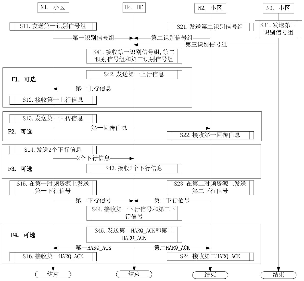
[0157] Embodiment 1 illustrates the flow chart of UE maintaining connection with multiple cells, as shown in the attached figure 1 shown. attached figure 1 Among them, cell N1 is the primary serving cell of UE U4. N1 cell, N2 cell and N3 cell are respectively maintained by 3 base stations. attached figure 1 , the steps in box F1, box F2, box F3 and box F4 are optional steps respectively.

[0158] For N1, send the first identification signal group in step S11, receive the first uplink information in step S12, send the first backhaul information in step S13, send two downlink information in step S14, and send the first uplink information in step S15. The first downlink signal is sent on the first time-frequency resource, and the first HARQ_ACK is received in step S16.

[0159] For N2, send the second identification signal group in step S21, receive the first return information in step S22, send the second downlink signal on the second time-frequency resource in step S23, an...

Embodiment 2

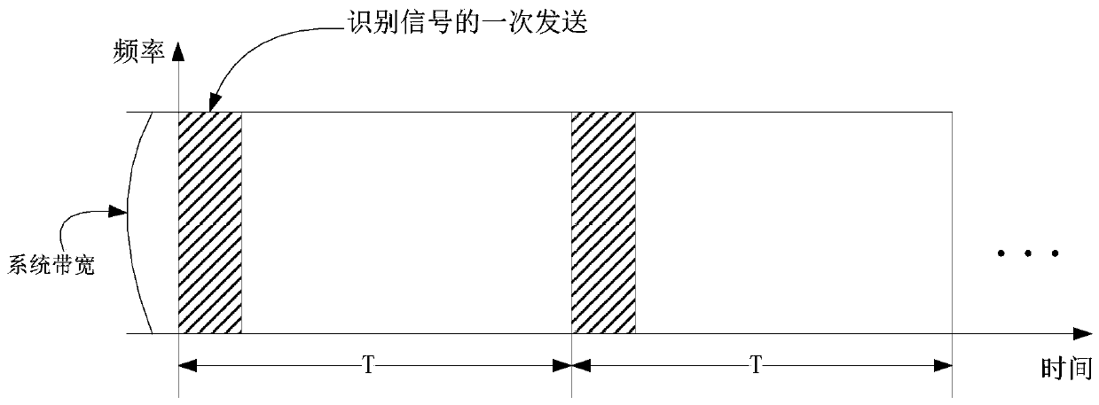
[0170] Embodiment 2 illustrates a schematic diagram of time resources and frequency resources occupied by an identification signal, as shown in the attached figure 2 shown. attached figure 2 In , the square marked with a slash is the time-frequency block occupied by one transmission of an identification signal.

[0171] In Embodiment 2, the identification signal is sent periodically, and the sending period is T (in milliseconds), where T is a positive rational number.

[0172] As a sub-embodiment 1 of Embodiment 2, each identification signal of the identification signal group in the present invention appears only once within a sending cycle.

[0173] As a sub-embodiment 2 of Embodiment 2, one transmission of the identification signal occupies W time windows in the time domain, where W is a positive integer greater than 1.

[0174] As a sub-embodiment 3 of Embodiment 2, one transmission of the identification signal occupies the attached figure 2 Part of the resource unit...

Embodiment 3

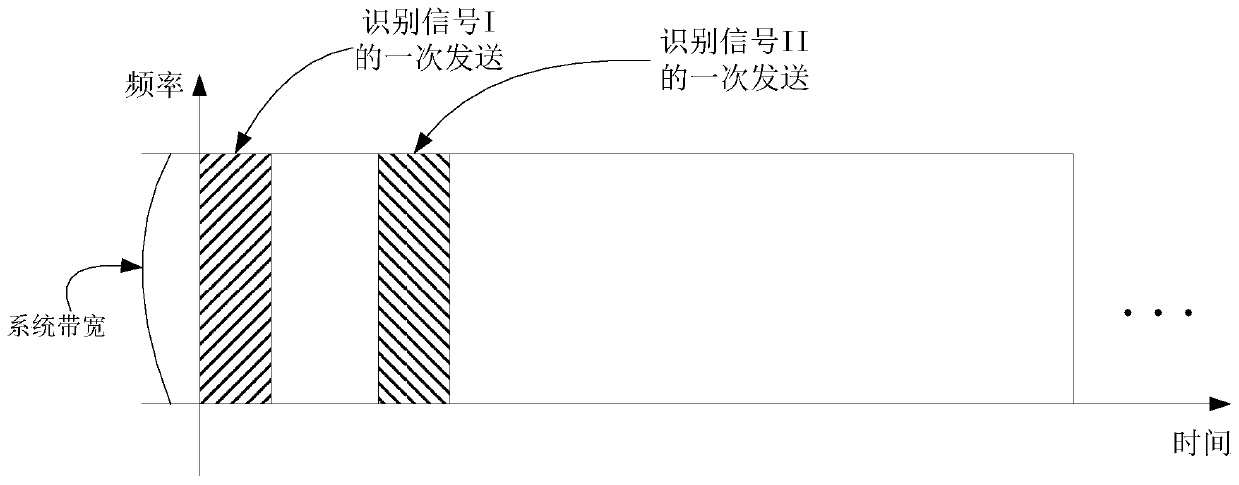
[0178] Embodiment 3 illustrates a schematic diagram of time resources and frequency resources occupied by two identification signals, as shown in the attached image 3 shown. attached image 3 In the figure, the square marked by the slash is the time-frequency block occupied by one transmission of an identification signal, that is, the identification signal I, and the square marked by the backslash is the time-frequency block occupied by one transmission of an identification signal, that is, the identification signal II .

[0179] In Embodiment 3, the identification signal I and the identification signal II respectively occupy different (one or more) time windows.

[0180] As a sub-embodiment 1 of Embodiment 3, an identification signal is sent once (ie aperiodically).


PUM


Abstract

The invention provides a communication method and a communication device in large-scale MIMO. In one embodiment, the UE respectively receives L downlink signals on L time-frequency resources, and theL downlink signals are respectively sent by L cells, wherein the frequency bands, which can be used for downlink transmission, of the L cells are all or partially overlapped, the downlink signal comprises at least one of {downlink data and downlink control signaling}, L is a positive integer greater than 1, and the L time-frequency resources are pairwise orthogonal. By using the technical scheme provided by the invention, the coverage problem of the broadcast signals sent by the multi-antenna base station is avoided, the inter-cell interference is reduced, the inter-cell service volume is balanced, the overhead of physical layer signaling is reduced, and the transmission efficiency is improved.

Description

[0001] This application is a divisional application of the following original application: [0002] -- Filing date of the original application: November 27, 2015 [0003] --Application number of the original application: 201510852656.0 [0004] --The name of the invention of the original application: a communication method and device in large-scale MIMO technical field [0005] The present invention relates to a solution for simultaneously maintaining connections between a UE (User Equipment, user equipment) and multiple cells in the technical field of mobile communications, and in particular to a solution for simultaneously maintaining connections between a UE and multiple cells in a scenario where multiple antennas are deployed on the base station side . Background technique [0006] In a traditional 3GPP-3rd Generation Partner Project (3GPP-3rd Generation Partner Project) cellular network system, a UE can usually only maintain a connection with one serving cell on a giv...

Claims


Application Information

Patent Timeline
Patent Type & Authority Applications(China)
IPC IPC(8): H04B7/06H04W28/02
CPCH04W76/15H04B7/0413H04W72/0453H04W72/23H04W28/02Y02D30/70
Inventor 张晓博
Owner SHANGHAI LANGBO COMM TECH CO LTD
Why Eureka
Try Eureka