
Textile fabric printing and dyeing method

A technology of textile fabrics and fabrics, which is applied to the processing of textile materials, the processing of textile material drums, and the fixing of chemicals in textile materials. Effects that enhance effects and deepen color depth and richness

Inactive Publication Date: 2020-10-30
杜丹
View PDF1 Cites 3 Cited by
  • Summary
  • Abstract
  • Description
  • Claims
  • Application Information

AI Technical Summary

Problems solved by technology

[0003] There are also some technical solutions in the prior art, such as the Chinese patent application number CN202010226380.6, which includes a base, a printing and dyeing box, a heating resistance wire and a printing and dyeing roller arranged inside the printing and dyeing box, and a printing and dyeing box is installed at the center of the top of the base. There are cavities on both sides of the inside of the printing and dyeing box, and a heating resistance wire with a serpentine structure is installed inside the cavity; the fabric is printed and dyed through the set printing and dyeing roller, and at the same time, the set heating resistance wire is heated to heat the fabric. Heating printing and dyeing; however, in this scheme, only the printing and dyeing rollers are used to print and dye the fabric, and the heating resistance wire is used to heat the printing and dyeing area on the fabric. When the fabric passes through the printing and dyeing roller, the pattern printed and dyed on the fabric may be shallow, resulting in a pattern after printing and dyeing. Fuzzy, which affects the aesthetics of the fabric after printing and dyeing. At the same time, the passing speed of the fabric is limited by the printing and dyeing roller when the fabric is printed and dyed by the printing and dyeing roller. not tall

Method used


Image

  • Textile fabric printing and dyeing method
  • Textile fabric printing and dyeing method
  • Textile fabric printing and dyeing method

Examples


Embodiment approach

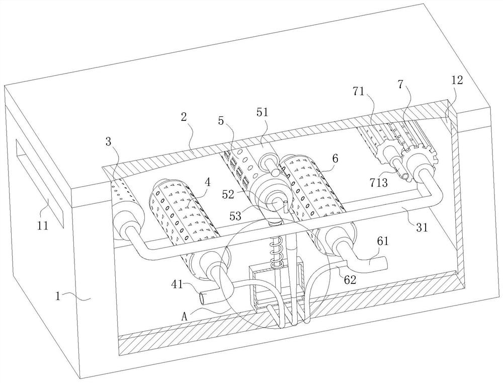
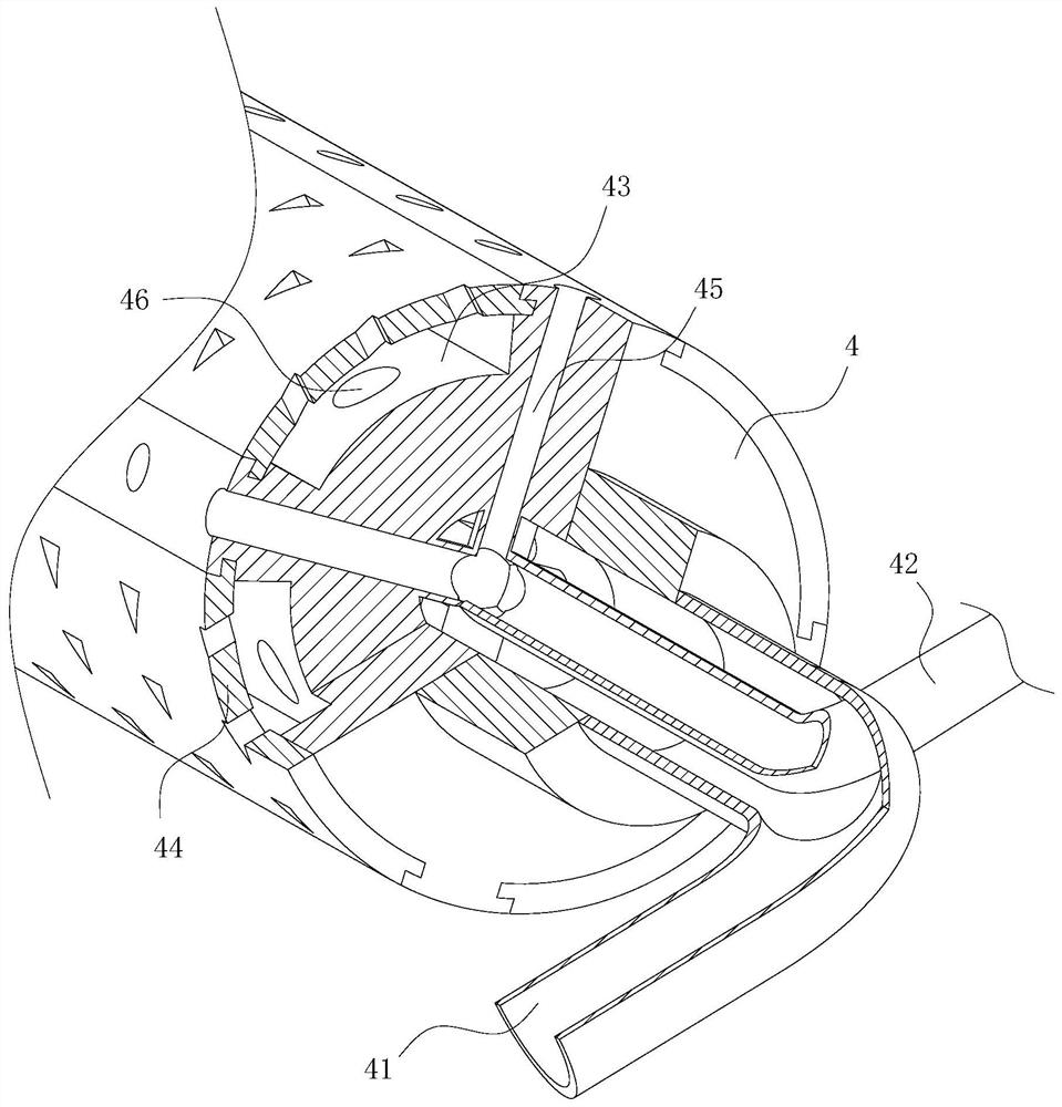
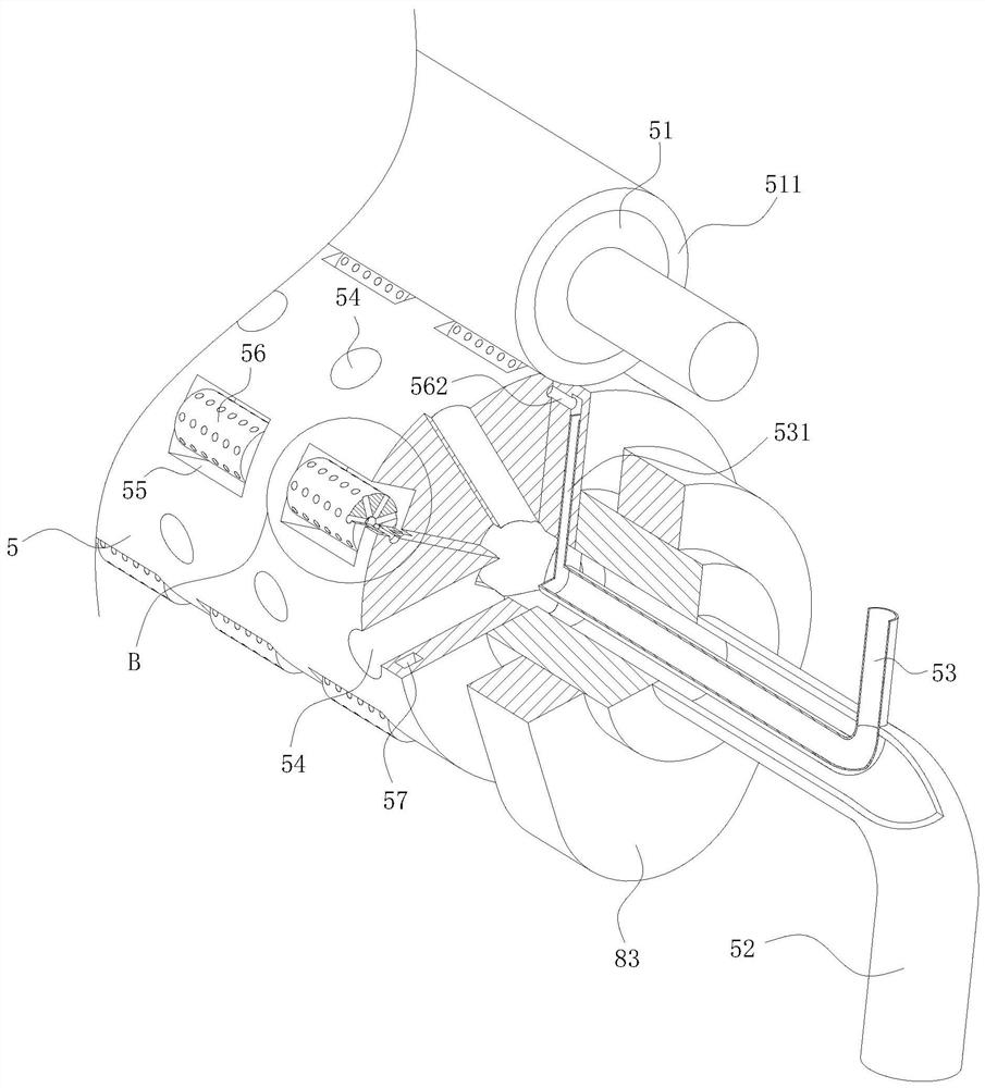
[0038] As an embodiment of the present invention, a squeeze roller 51 is installed on the main body 1; the squeeze roller 51 is located directly above the middle roller 5, and the squeeze roller 51 is in close contact with the middle roller 5; The surface of the roller 51 is covered with a sponge layer 511; the surface of the intermediate roller 5 is uniformly provided with a through hole 4 54; the inside of the intermediate roller 5 is provided with a cavity 2; the through hole 4 54 communicates with the cavity 2; Pipe four 52 is installed on the intermediate roller 5; the pipe four 52 communicates with cavity two; a cam 83 is installed on the rotating shaft of the intermediate roller 5; a box body 8 is installed in the main body 1; Movable plate 84 is installed in body 8; Keep sealing between described movable plate 84 and box body 8; Movable bar 81 is installed on described movable plate 84; The top of described movable bar 81 contacts with cam 83; A spring 82 is installed ...


PUM


Abstract

The invention belongs to the technical field of textile fabric processing, and particularly relates to a textile fabric printing and dyeing method. The textile fabric printing and dyeing method comprises the following steps that S1, dust removal treatment is performed on a textile fabric to clear dust and broken fibers attached to the surface of the textile fabric, and then the cleaned fabric is wound around a material roller; and S2, the fabric treated in the step 1 penetrates into a printing and dyeing device, and the fabric after penetrating through the printing and dyeing device directly enters secondary drying equipment to be dried to obtain the finished printed and dyed fabric. According to the textile fabric printing and dyeing method, by repeatedly printing and dyeing the fabric, the printing and dyeing effect of the fabric is improved, meanwhile, the printing and dyeing speed of the fabric is increased, and the printing and dyeing efficiency is improved.

Description

technical field [0001] The invention belongs to the technical field of textile fabric processing, in particular to a textile fabric printing and dyeing method. Background technique [0002] Polyester is the world's largest and most widely used synthetic fiber variety, and polyester accounts for more than 60% of the world's synthetic fiber production. It is widely used in textiles such as clothing, bedding, various decorative fabrics, special fabrics for national defense and other industrial fiber products, such as filter materials, insulating materials, tire cords, conveyor belts, etc. With the sustained and rapid growth of the domestic economy and the continuous improvement of the consumption capacity of domestic residents, the demand for polyester staple fibers in the domestic region is also increasing. The production capacity of polyester series products in China is growing at an alarming rate, and the rapid growth of polyester fiber production capacity has made China gr...

Claims


Application Information

Patent Timeline
IPC IPC(8): B41F15/08B41F15/12B41F13/06D06B1/02D06B15/02D06B15/09D06B19/00D06B23/02D06G1/00
CPCB41F13/06B41F15/0836B41F15/12D06B1/02D06B15/02D06B15/09D06B19/0005D06B23/026D06G1/00
Inventor 杜丹李家豪
Owner 杜丹
Learn More