Microbial exhaust gas purification

A waste gas purification and microbial technology, which is applied in the direction of air quality improvement, chemical instruments and methods, combined devices, etc., can solve the problems of high cost and high energy consumption of waste gas treatment equipment, so as to improve the purification effect, strengthen the purification effect, reduce the cost effect

Inactive Publication Date: 2019-12-31
重庆展亚环保工程有限公司
View PDF6 Cites 0 Cited by
  • Summary
  • Abstract
  • Description
  • Claims
  • Application Information

AI Technical Summary

Problems solved by technology

[0004] The present invention intends to provide a microbial waste gas purification to solve t

Method used


Image

  • Microbial exhaust gas purification
  • Microbial exhaust gas purification

Examples


Embodiment 1

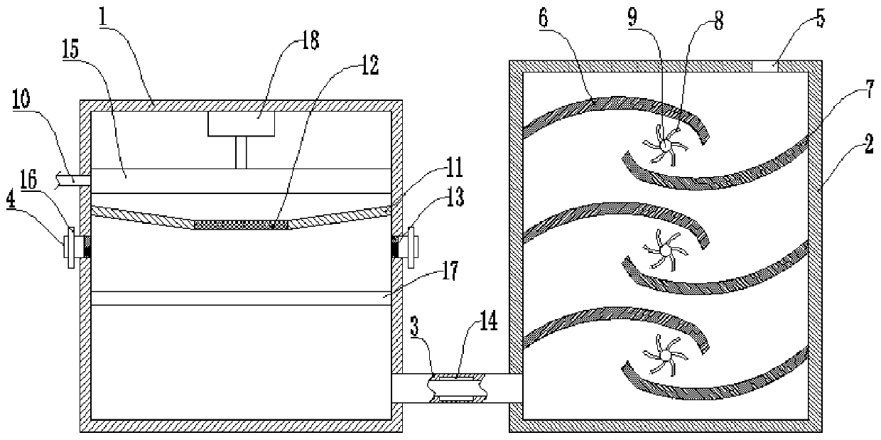
[0031] Basic as attached figure 1 Shown: purification of microbial waste gas, including dust suppression box 1 and degradation box 2, and pipeline 3 is fixedly connected between dust suppression box 1 and degradation box 2, and pipeline 3 connects dust suppression box 1 and degradation box 2, and the inner wall of pipeline 3 is set There is a heating wire 14; there is an inlet 4 on the dust suppression box 1, and there are two inlets 4, and the two inlets 4 are respectively located on both sides of the dust suppression box 1; a screen 13 is fixed in the inlet 4. The top of the degradation box 2 is provided with an outlet 5 .

[0032] The dust suppression box 1 is provided with a dust suppression mechanism for removing suspended particulate pollutants in the exhaust gas. The dust suppression mechanism includes a partition 11 fixed in the body of the dust suppression box 1 and a water inlet pipe 10 connected with the dust suppression box 1. The partition 11 is located at the wat...

Embodiment 2

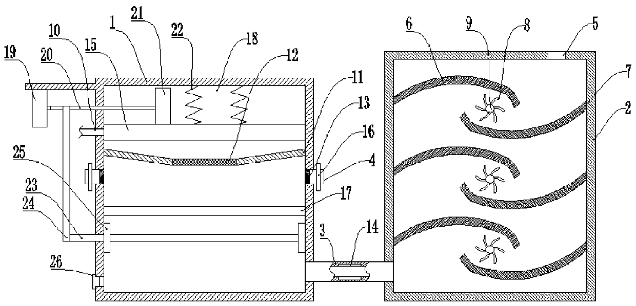
[0042] Basic as attached figure 2 As shown, the structure and implementation of Embodiment 2 are basically the same as Embodiment 1. The difference is that the power mechanism includes a motor 19 fixed to the outer wall of the dust suppression box 1 and a linkage shaft 20 connected in rotation with the dust suppression box 1. The shaft 20 is affixed to the output shaft of the motor 19, and the linkage shaft 20 is affixed with a cam 21 against the lifting plate 15, and the cam 21 is located above the lifting plate 15; a spring 22 is affixed between the lifting plate 15 and the dust box 1 .

[0043] A circular shaft 23 is rotatably connected to the dust suppression box 1, and the circular shaft 23 is located below the second one-way valve 17; a stretched belt 24 is sleeved between the circular shaft 23 and the linkage shaft 20, and the circular shaft 23 is provided with a dust-suppression valve. There are two sponge blocks 25 attached to the inner wall of the case 1, and there...


PUM


Abstract

Relating to the technical field of exhaust gas purification, the invention discloses a microbial exhaust gas purification device, which comprises a dust falling box and a degradation box, and a pipeline arranged between the dust falling box and the degradation box. The dust falling box is equipped with inlets, and the degradation box is equipped with an outlet. The dust falling box is internally equipped with a dust falling box mechanism for removing suspended granular pollutants in exhaust gas. The degradation box is internally equipped with a plurality of degradation mechanisms, each degradation mechanism comprises an upper flow guide plate, a lower flow guide plate and a plurality of filler carriers which are used for bearing microbial filler and enabling exhaust gas to pass through, the upper flow guide plates and the lower flow guide plates are fixedly connected to the inner wall on both sides of the degradation box in a staggered mode, and the filler carriers are located betweenthe upper flow guide plates and the lower flow guide plates. The scheme mainly solves the problems of high energy consumption and high cost in existing exhaust gas treatment equipment.

Description

technical field [0001] The invention relates to the technical field of waste gas purification. Background technique [0002] Exhaust gas refers to the poisonous and harmful gas emitted by human beings in the process of production and life; especially in chemical plants, steel plants, pharmaceutical factories, coking plants and oil refineries, etc., the exhaust gas emitted has a strong smell, which seriously pollutes the environment and affects human health. [0003] At present, traditional waste gas treatment equipment includes spray towers, sieve plate towers, bubble towers, etc. Although they can effectively treat waste gas, they have the problems of large footprint, high energy consumption, and high cost, and are not suitable for small and medium-sized enterprises. . Contents of the invention [0004] The present invention intends to provide a microbial waste gas purification to solve the problems of high energy consumption and high cost of the current waste gas treatm...

Claims


Application Information

Patent Timeline
IPC IPC(8): B01D53/84B01D50/00
CPCB01D53/84B01D50/60Y02A50/20
Inventor 何修建周忠梅李小娅任林
Owner 重庆展亚环保工程有限公司
Why Eureka
Try Eureka