Movable steel strand bending and clamping combination tool

A technology of combining tools and steel strands, applied in the direction of overhead line/cable equipment, etc., can solve the problems of increased work difficulty, difficult bending, unguaranteed process requirements, etc., to improve the quality and process level, and improve the on-site construction. The effect of efficiency

Pending Publication Date: 2019-12-31
LANGFANG POWER SUPPLY COMPANY STATE GRID JIBEI ELECTRIC POWER COMPANY +1
View PDF0 Cites 1 Cited by
  • Summary
  • Abstract
  • Description
  • Claims
  • Application Information

AI Technical Summary

Problems solved by technology

Due to the greater rigidity of the large cross-section steel strand, it is difficult to bend, and often requires repeated bending many times to bend successfully, and it is easy to cause scratches
The bent steel strand and the tongue plate are put into the wedge-shaped clamp, which cannot be tightened by manpower at all, and can only be done by hammering, which will cause the galvanized layer of the wedge-shaped clamp to be damaged by the beating and increase the risk of corrosion. possible
It is time-consuming and labor-intensive to draw wires by on-site personnel, and the process requirements cannot be guaranteed
[0003] The current on-site wire production equipment is single, especially for large-section steel strands, simple tools can no longer meet the requirements, and manual bending and clamping are often used
Due to the strong rigidity of the large cross-section steel strands, it is not easy to bend, which increases the difficulty of work and reduces the efficiency
When the bent steel strand is clamped, it is not easy to put it into the wedge-shaped clamp together with the tongue plate, and it cannot be tightly fitted with the tongue plate, resulting in the production quality and technical level of the pull wire cannot meet the requirements

Method used


Image

  • Movable steel strand bending and clamping combination tool
  • Movable steel strand bending and clamping combination tool
  • Movable steel strand bending and clamping combination tool

Examples


Embodiment Construction

[0022] The present invention will be further described in detail below with reference to the drawings and embodiments. It can be understood that the specific embodiments described here are only used to explain the related invention, but not to limit the invention. In addition, it should be noted that, for ease of description, only the parts related to the invention are shown in the drawings.

[0023] It should be noted that the embodiments of the present invention and the features in the embodiments can be combined with each other if there is no conflict. Hereinafter, the present invention will be described in detail with reference to the drawings and in conjunction with the embodiments.

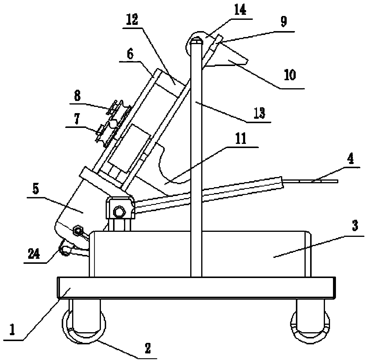
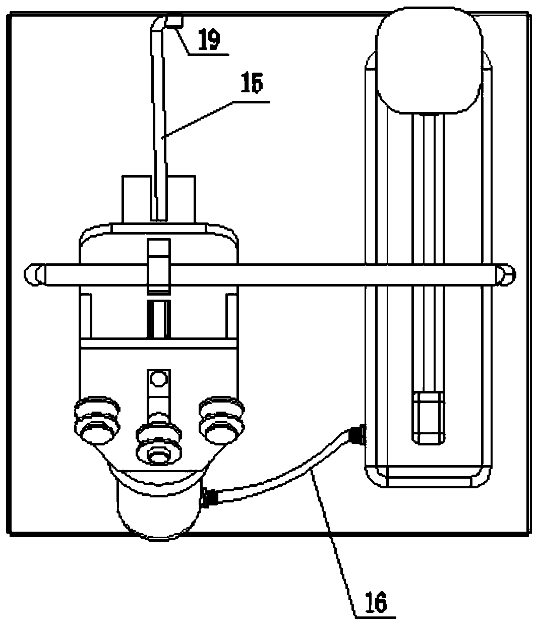
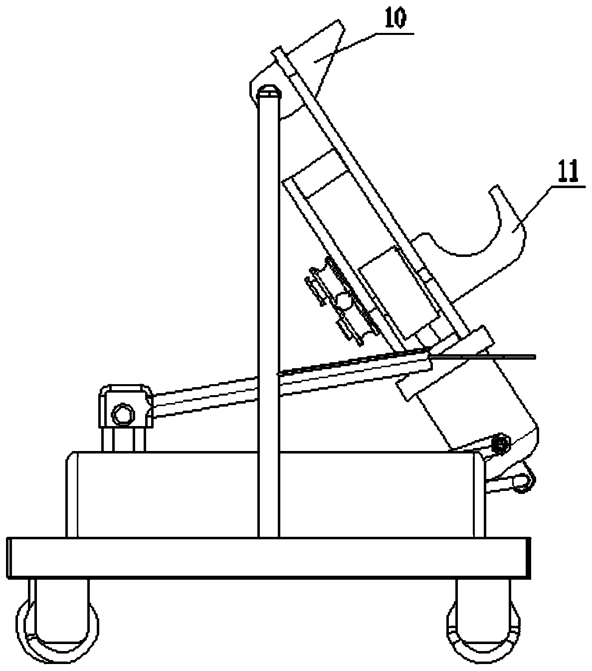
[0024] Please refer to figure 1 , figure 2 with image 3 , A mobile steel strand bending and clamping combination tool, comprising a base 1, four corners of the bottom of the base 1 are installed with casters 2, the center of both sides of the base 1 are welded with a door frame 13, so The upp...


PUM


Abstract

The invention discloses a movable steel strand bending and clamping combination tool. The movable steel strand bending and clamping combination tool comprises a base, wherein trundles are installed atfour corners of the bottom of the base, door-shaped frames are installed on the centers of the two sides of the base in a welding mode, and a wedge-shaped wire clamping baffle is installed to the bottom of the upper end of a clamping bottom plate. The bending of the steel strand and the clamping work of the steel strand and a tongue plate in a wedge-shaped wire clamp can be achieved, and in particular, the effect of bending and clamping on the large-section steel strand is more remarkable, the application of the result can overcome the damage of the wedge-shaped wire clamp zinc coating causedby the method that field construction personnel wastes time and energy when the steel strand is bent and a method of knocking the wedge-shaped wire clamp through a hammer to enable the steel strand and the tongue plate to be clamped in the wedge-shaped wire clamp, and meanwhile, the problems of personnel scratch caused by the rigid cause when the steel strand is bent manually is avoided as well.The manufacturing quality and the process level of the stay wire is improved as well while the field construction efficiency is improved by the movable steel strand bending and clamping combination tool, and the help is provided for the construction site of scattered distribution networks.

Description

Technical field [0001] The invention relates to the field of steel strand manufacturing equipment, and in particular to a mobile steel strand bending and clamping combination tool. Background technique [0002] As the load of the distribution line increases, the cross section of the conductor also increases. In order to meet the requirements of safe operation of the line, the cross-sections of the steel strands used in the line terminals and corners are also getting larger and larger, from the 35 and 50 cross-sections to the 80 and 100 cross-sections. With the increase of the cross-section of steel strands, the existing on-site wire-drawing tools can only meet the requirements for the production of small cross-section wires of 50 and below, and on-site tools for large-section wires have not yet appeared. Due to the greater rigidity of large cross-section steel strands, it is difficult to bend, and often requires repeated bending many times to bend successfully, and it is easy to...

Claims


Application Information

Patent Timeline
Patent Type & Authority Applications(China)
IPC IPC(8): B21F1/00H02G1/04
CPCB21F1/004H02G1/04
Inventor 冀维成宁琦杨占林高玉华侯凤山张斌庄宝山王华丽刘玉超
Owner LANGFANG POWER SUPPLY COMPANY STATE GRID JIBEI ELECTRIC POWER COMPANY
Why Eureka
Try Eureka