Milling machine automatic feeding and discharging equipment, using method and application thereof

A technology of automatic loading and unloading and equipment, which is applied in metal processing and other directions, and can solve the problems of low automation, low production efficiency, and high labor intensity.

Pending Publication Date: 2019-12-31
安徽一众精密轴业有限公司
View PDF3 Cites 5 Cited by
  • Summary
  • Abstract
  • Description
  • Claims
  • Application Information

AI Technical Summary

Problems solved by technology

[0007] The invention provides an automatic loading and unloading device for a milling machine. The purpose of the present invention is to solve the problem of manual loading and unloading one by one in the process of milling the end face and punching the center hole of the existing shaft parts using a milling machine, resulting in high labor intensity. Low degree of automation and low production efficiency

Method used


Image

  • Milling machine automatic feeding and discharging equipment, using method and application thereof
  • Milling machine automatic feeding and discharging equipment, using method and application thereof
  • Milling machine automatic feeding and discharging equipment, using method and application thereof

Examples


Embodiment Construction

[0046] The present invention will be further described below in conjunction with specific embodiments.

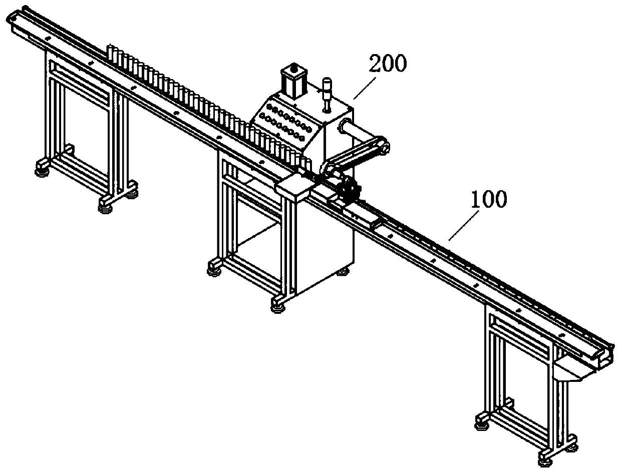
[0047] figure 1 It shows the overall structural view of the automatic loading and unloading equipment of the milling machine in this embodiment, which is mainly composed of two parts, including the conveying device 100 and the retrieving manipulator 200 arranged on one side of the conveying direction of the conveying device 100 . Among them, the conveying device 100 is used for arranging and conveying the workpieces, that is, to convey the workpieces to be processed one by one to the designated position, so that the retrieving manipulator 200 can grab and send the processed workpieces to the next process; the reclaiming manipulator 200 uses The workpiece to be processed at the specified position on the conveying device 100 is grabbed and sent to the milling machine for processing, and the processed workpiece is retrieved from the milling machine to the conveying device 100 ...


PUM


Abstract

The invention discloses milling machine automatic feeding and discharging equipment, a using method and application thereof, and belongs to the field of milling machine supporting equipment. The milling machine automatic feeding and discharging equipment comprises a conveying device and a picking manipulator arranged on one side of the conveying direction of the conveying device, the conveying device comprises a belt conveying mechanism, and a positioning controlling mechanism located on the belt conveying mechanism, the belt conveying mechanism is used for conveying workpieces, and a pickingposition is arranged in the conveying direction of the belt conveying mechanism; and the upper side of the picking position in the conveying direction is provided with a to-be-processed area, the lower side of the picking position in the conveying direction is provided with a finished product area, the positioning controlling mechanism is used for controlling the workpieces placed vertically in the to-be-processed area to be put down and conveyed to the picking position one by one, the picking manipulator is used for grasping the to-be-processed workpieces at the picking position of the belt conveying mechanism to be sent to a milling machine, or the workpieces after processing in the milling machine are sent back to the picking position of the belt conveying mechanism. The milling machineautomatic feeding and discharging equipment can realize automatic feeding and discharging of milling machine processing, effectively reduces the labor intensity, improves the production efficiency, and facilitates the automatic production.

Description

technical field [0001] The invention belongs to the field of auxiliary equipment for milling machines, and relates to automatic loading and unloading of metal bars during milling machine processing, and more specifically relates to an automatic loading and unloading equipment for milling machines and its use method and application. Background technique [0002] Shaft parts are essential transmission parts in mechanical equipment, and are usually processed from metal bars. In the washing machine, the rotating shaft is an important component that supports the drum, transmits power, and completes the laundry function. The shaft of the washing machine has the characteristics of high-speed rotation and torque transmission during operation, and the working environment is harsh, generally with moisture and dust. In addition, both It rotates positively and negatively, bears alternating torque, and ensures the rotation accuracy to reduce noise and reach the required fatigue limit. T...

Claims


Application Information

Patent Timeline
Patent Type & Authority Applications(China)
IPC IPC(8): B23Q7/00B23Q7/04
CPCB23Q7/00B23Q7/043B23Q7/046
Inventor 储士钊王水平
Owner 安徽一众精密轴业有限公司
Why Eureka
Try Eureka