Circular material mechanical grabbing device

A technology for mechanical grasping and materials, which is applied in the field of mechanical grasping devices and circular material mechanical grasping devices, which can solve problems such as unreliable clamping, fixed clamping range, and stuck faults of power sources, etc., to achieve stable and reliable clamping , avoid sticking, and simplify the mechanism

Pending Publication Date: 2019-12-31
AEROSUN CORP
View PDF1 Cites 2 Cited by
  • Summary
  • Abstract
  • Description
  • Claims
  • Application Information

AI Technical Summary

Problems solved by technology

So many mechanism links not only make the structure complex and the cumulative error is large, so the clamping is not reliable, but also the moving pair adjacent to the power source is prone to stuck faults, which must be avoided during the transfer of polluting solid waste
In addition, this technical solution also has the following disadvantages: 1) The grabbing action of the hook rod relies on the centripetal sliding drive of the cross slider along the sliding rod, so it is necessary to reserve radial driving space, and the structure is not compact; 2) The hook rod 121 The clamping range is fixed and the adaptability is poor

Method used


Image

  • Circular material mechanical grabbing device
  • Circular material mechanical grabbing device
  • Circular material mechanical grabbing device

Examples


Embodiment Construction

[0024] The following will clearly and completely describe the technical solutions in the embodiments of the present invention with reference to the drawings in the embodiments of the present invention.

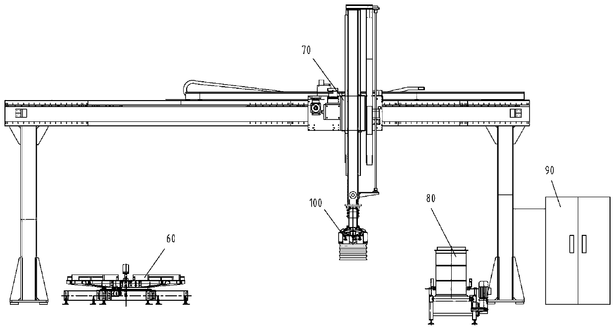
[0025] The circular material mechanical grasping device of this embodiment is applied to figure 1 In the polluting solid waste transfer system shown. The system includes a steel drum conveying roller table 80 and a material storage table 60 spaced apart from each other. Above the conveying roller table 80 and the material storage table 60, a truss composed of guide rail beams supported on columns at both ends is installed. The truss is equipped with horizontally movable The manipulator 70, the manipulator 70 has a lifting arm with a circular material mechanical grabbing device 100 at the lower end.

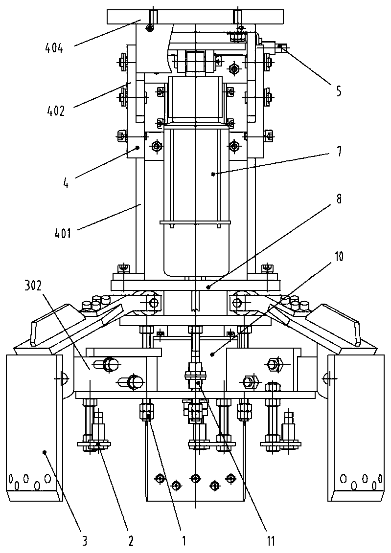
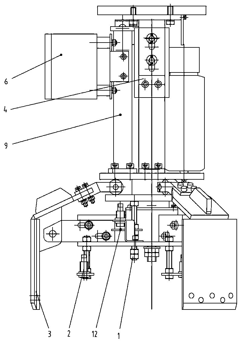
[0026] The specific structure of the circular material mechanical grasping device 100 is as follows: Figure 2 to Figure 6 As shown, it includes a telescopic support 4 whose upp...


PUM


Abstract

The invention discloses a circular material mechanical grabbing device, and belongs to the technical field of solid waste treatment. The device comprises a performer bracket for mounting a linear performer capable of vertically extending out and drawing back, wherein the performer bracket is fixedly connected to a ring-shaped upper circular disc; a pushing rod of the linear performer passes through the upper circular disc and is fixedly connected to the center of a lower circular disc; three fixed arms which extend in a radial direction are uniformly distributed and fixed in the peripheral direction of the lower circular disc; the outer ends of the fixed arms are hinged with the middle part of a clamping arm; the clamping arm defines a bent arm shape through a radial lower tilting arm anda vertical grabbing arm which are connected into an integer, the three grabbing arms surround a clamping circle; and the inner end of the lower tilting arm is equipped with a horizontal shaft roller which is positioned in a peripheral slide slot of the upper circular disc to define movable fit. Clamping of the circular material mechanical grabbing device is realized through relative perpendicularmotion of the upper circular disc and the lower circular disc, and radial drive is not needed, so that the structure is compact; and a structure that the roller at the inner end of the clamping arm isrestrained by the upper disc and the lower disc combines a movable pair with a hinge pair, so that the mechanism is obviously simplified, and therefore, blocking can be effectively avoided, and stable and reliable clamping is guaranteed.

Description

technical field [0001] The invention relates to a mechanical grabbing device, in particular to a circular material mechanical grabbing device, which belongs to the technical field of solid waste treatment. Background technique [0002] In order to reduce the impact of polluting waste on the environment, it is usually necessary to minimize the treatment of polluting solid waste, that is, to carry out compaction and volume reduction treatment in each link. For example, steel drums containing compactable dry pollutants are super compacted to produce drum cakes, which are then placed in steel drums for secondary packaging for cement fixation. In this process, in order to improve the filling rate of pollutants and reduce the volume of pollutants to be disposed of, it is necessary to put several barrel cakes of appropriate weight and height into a steel drum through the grabbing device of the barrel cake optimization system to optimize the amount of waste in the steel barrel. spa...

Claims


Application Information

Patent Timeline
Patent Type & Authority Applications(China)
IPC IPC(8): B65G47/90
CPCB65G47/902
Inventor 杨慧王小安王强孙广仁
Owner AEROSUN CORP
Why Eureka
Try Eureka