

Intelligent, green and environmental-friendly integrated building structure
It is a technology of green environmental protection and building structure, which is applied in the direction of building components, building structure, construction, etc. It can solve the problems of large amount of cement sand, dust pollution, and inability to reuse, so as to reduce construction waste, avoid dust pollution, and facilitate The effect of reuse
- Summary
- Abstract
- Description
- Claims
- Application Information
AI Technical Summary
Problems solved by technology
Method used
Image

Examples
Embodiment 1
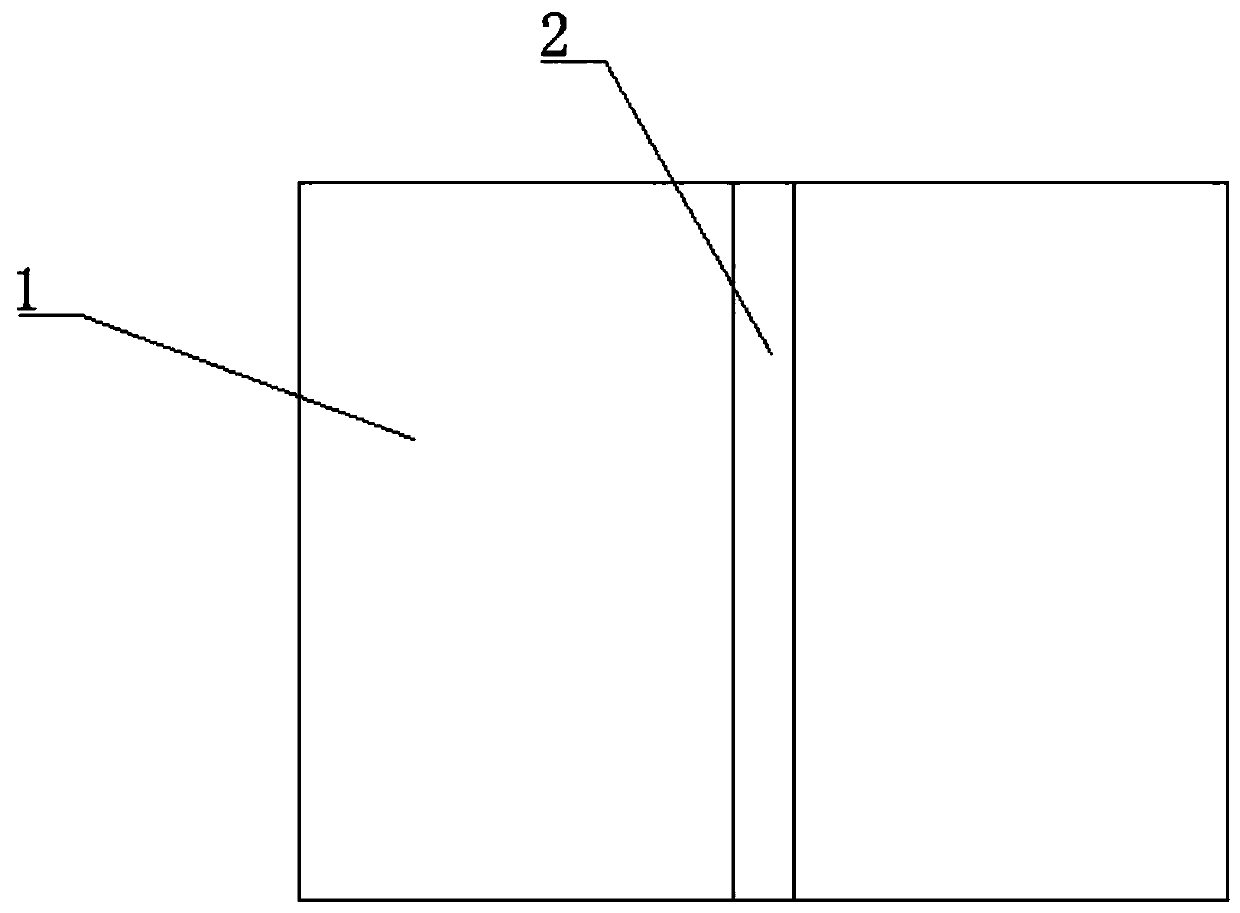
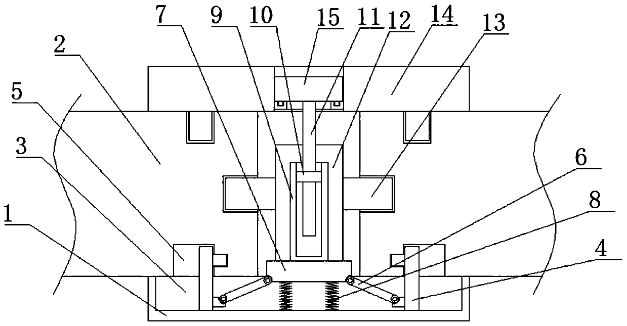
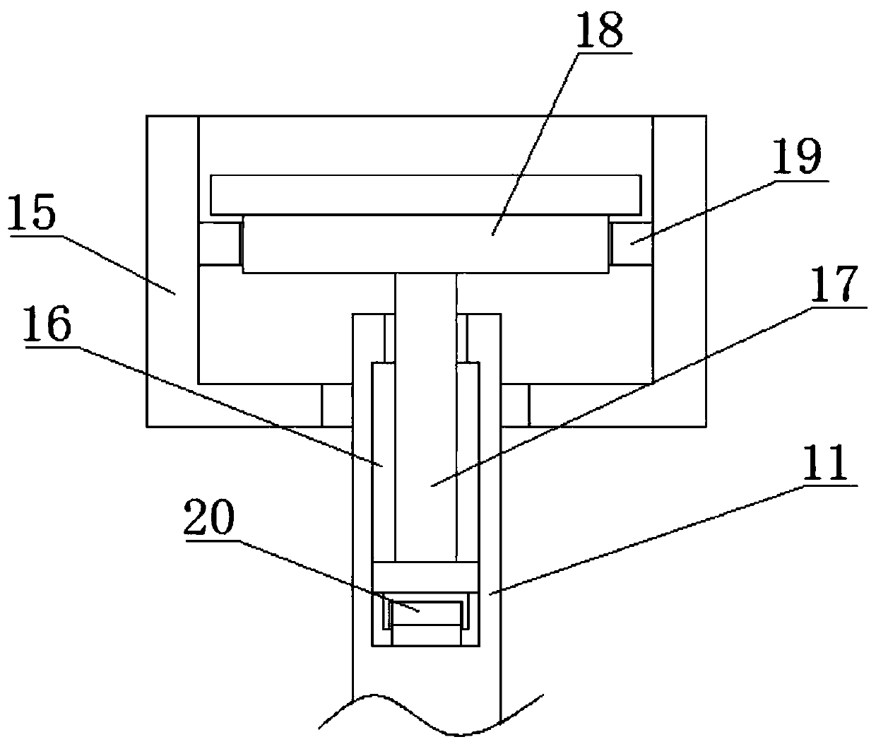
[0021] see Figure 1-3 , this embodiment provides an intelligent green environment-friendly integrated building structure, including two partition boards 1, the same first splint 2 is clamped on the two partition wall boards 1, and one side of the first splint 2, etc. A plurality of moving grooves 3 are provided at intervals, and a moving plate 7 is slidably connected to the inner wall of the moving groove 3. One side of the moving plate 7 extends to the outside of the first splint 2 and is located between two partition wall panels 1. The moving plate 7 A screw 11 is threaded on one side of the two partition boards 1, and the same second splint 14 is mounted on the other side of the two partition boards 1, and a plurality of mounting holes are opened at equal intervals on the second splint 14, and the clamping in the mounting holes is limited. Position cover 15, one end of the screw rod 11 extends into the limit cover 15 and is rotatably connected with one side of the limit co...
Embodiment 2
[0023] In the present invention, one side of the first splint 2 is equidistantly fixed with a plurality of connection plates 12, and the plurality of connection plates 12 are located between two partition wall panels 1, and the plurality of connection plates 12 and the plurality of screw rods 11 are alternately arranged. , Both sides of the connecting plate 12 are fixedly installed with clamping plates 13, and one side of the clamping plate 13 is clamped with one side of the partition wall panel 1, so as to prevent the possibility of sliding between the partition wall panels 1.
[0024] In the present invention, a connection cover 9 is fixedly installed on one side of the moving plate 7, and a nut 10 is fixedly installed on the inner wall of the connection cover 9, and the other end of the screw rod 11 passes through the nut 10 and is threadedly connected with the nut 10, utilizing the self-locking of the thread principle The first splint 2 and the second splint 14 can be limit...
PUM
 Abstract
Description
Claims
Application Information