Building floor heat insulation structure

A technology of floor and thermal insulation layer, which is applied in the direction of floor, building structure, covering/lining, etc., can solve the problems of rough treatment of the ground floor, the flatness cannot meet the construction conditions of the thermal insulation layer, and the hollowing and cracking of the protective layer. To achieve the effect of increasing floor height, convenient process and reducing material consumption

Pending Publication Date: 2019-12-31
SHANGHAI SHENGKUI PLASTIC IND
View PDF0 Cites 4 Cited by
  • Summary
  • Abstract
  • Description
  • Claims
  • Application Information

AI Technical Summary

Problems solved by technology

Limited to the current building construction technology and actual construction conditions, the treatment of the base layer of the building is relatively rough, and the flatness generally cannot meet the construction conditions of the insulation layer, resulting in a cavity between the insulation layer and the base layer of the building after construction, which in turn causes Hollowing and cracking of the protective layer are common
In addition, in order to meet the flatness requirements of the protective layer, the thickness of the protective layer made of fine stone concrete and steel wire mesh needs to reach more than 40mm, so that the thickness of the floor insulation structure reaches 70-80mm, which has a great influence on the net height and material of the building. The consumption and the main structure load of the building have a very large impact, which needs to be solved urgently

Method used


Image

  • Building floor heat insulation structure

Examples


Embodiment Construction

[0025] The following descriptions of various embodiments refer to the accompanying drawings to illustrate specific embodiments in which the present invention can be implemented.

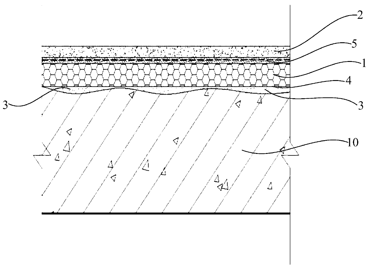
[0026] Such as figure 1 As shown, this embodiment discloses a floor insulation structure. The floor insulation structure includes an insulation layer 1, an armor layer 2 and a leveling layer 3. The armor layer 2 is arranged above the insulation layer 1, and the leveling layer 3 is used for It is connected to the base layer 10 of the floor, and the leveling layer 3 is arranged below the thermal insulation layer 1 . Lay the leveling layer 3 on the base layer 10 of the floor, and realize the leveling of the base layer 10 through the leveling layer 3, and then lay the insulation layer 1 on the top of the leveling layer 3, so as to avoid the unevenness of the original base layer after laying the insulation layer 1 on the base layer 10 of the building. And form the cavity with the insulation layer 1, then...


PUM

PropertyMeasurementUnit
thicknessaaaaaaaaaa
thicknessaaaaaaaaaa
thicknessaaaaaaaaaa

Abstract

The invention discloses a building floor heat insulation structure which comprises a protective surface layer and a heat insulation layer, wherein the protective surface layer is arranged on the heatinsulation layer. The building floor heat insulation structure also comprises a leveling layer, wherein the leveling layer is used for being connected onto a building floor base layer; the leveling layer is arranged under the heat insulation layer; the leveling layer and the protective surface layer are made of cement-based self-leveling mortar; and the heat insulation layer is made of grade A fireproof heat insulation materials. Through the additional arrangement of the leveling layer on the building floor base layer and in the middle between the building floor base layer and the heat insulation layer, the problem of protective surface layer cracking caused under the condition of great load receiving by the protective surface layer due to the building floor base layer flatness problem iseffectively solved; meanwhile, the goal of reducing the thickness of the whole building floor heat insulation structure from the original 70 to 80 mm to 30 to 50mm is achieved; the material consumption reduction is realized; the building main body structure load is reduced; the indoor storey height of a building is increased; the construction process is simple; the process is convenient and fast;and the operation is easy.

Description

technical field [0001] The invention relates to a floor heat preservation structure. Background technique [0002] The existing floor insulation structure includes an insulation layer arranged on the base layer of the floor, and a protective surface layer formed of fine stone concrete and steel wire mesh sheets arranged above the insulation layer. The insulation layer is mostly extruded board or inorganic insulation mortar. Limited to the current building construction technology and actual construction conditions, the treatment of the base layer of the building is relatively rough, and the flatness generally cannot meet the construction conditions of the insulation layer, resulting in a cavity between the insulation layer and the base layer of the building after construction, which in turn causes Hollowing and cracking of the protective layer are common. In addition, in order to meet the flatness requirements of the protective layer, the thickness of the protective layer m...

Claims


Application Information

Patent Timeline
Patent Type & Authority Applications(China)
IPC IPC(8): E04F15/12E04F15/18
CPCE04F15/12E04F15/18E04F2290/04
Inventor 刘丙强季良刘念界
Owner SHANGHAI SHENGKUI PLASTIC IND
Why Eureka
Try Eureka