Core formwork used for pouring top air passage of subway rail and construction method

A technology of rail top air duct and construction method, which is applied in the direction of formwork/formwork/work frame, building, building structure, etc., which can solve the problems of inconvenient demolition for workers, and achieve the advantages of small demolition workload, improved service life and easy demolition Effect

Active Publication Date: 2019-12-31
CRPCEC SHENZHEN ENG
View PDF4 Cites 2 Cited by
  • Summary
  • Abstract
  • Description
  • Claims
  • Application Information

AI Technical Summary

Problems solved by technology

This construction method reduces the number of construction links and avoids the occurrence of secondary entry, but there are the following problems: after the construction is completed, it is necessary to manually enter the interior of the air duct to remove the inner formwork support. Due to the small space in the air duct, it is inconvenient for workers to remove it

Method used


Image

  • Core formwork used for pouring top air passage of subway rail and construction method
  • Core formwork used for pouring top air passage of subway rail and construction method
  • Core formwork used for pouring top air passage of subway rail and construction method

Examples


Embodiment 1

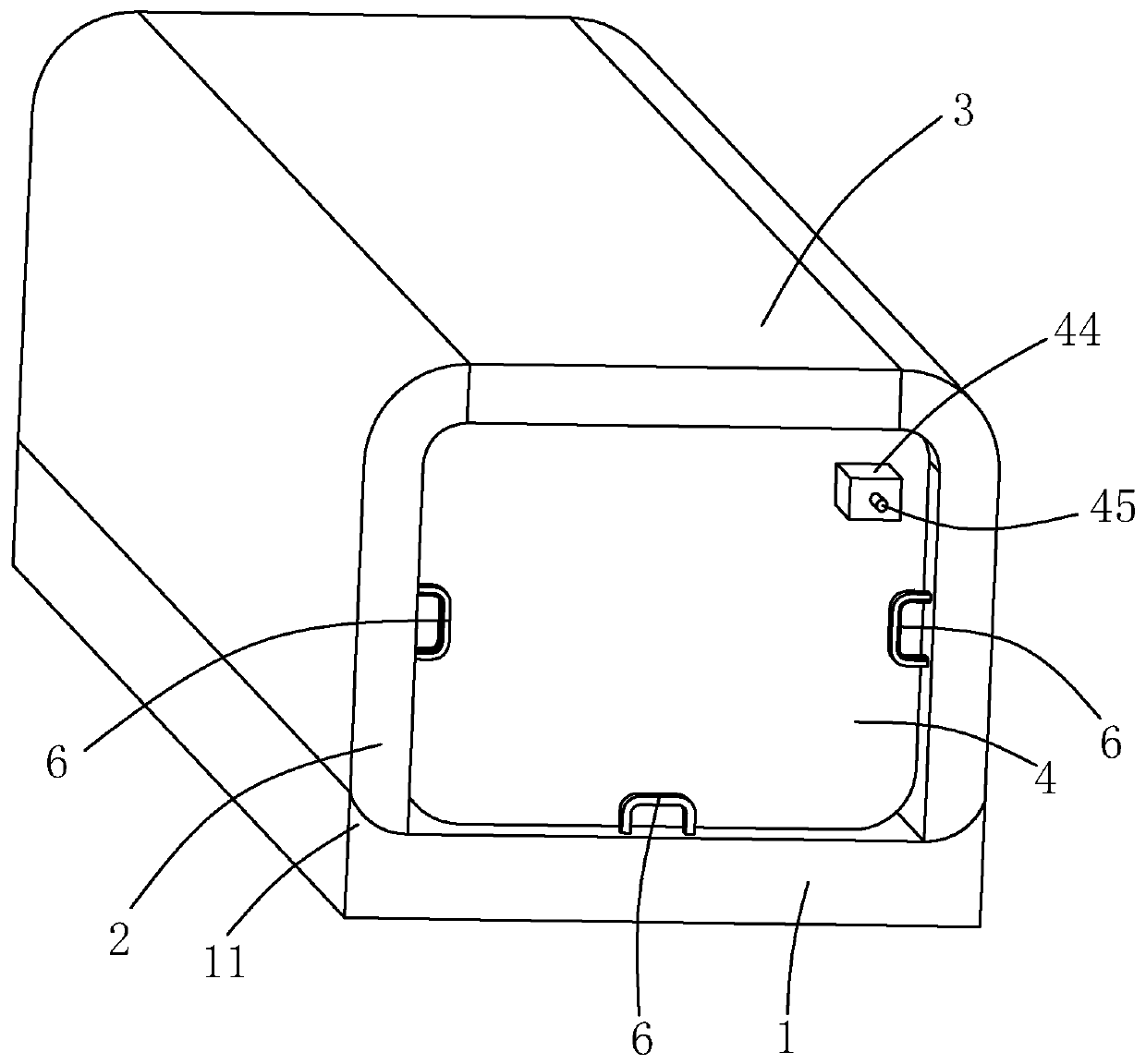
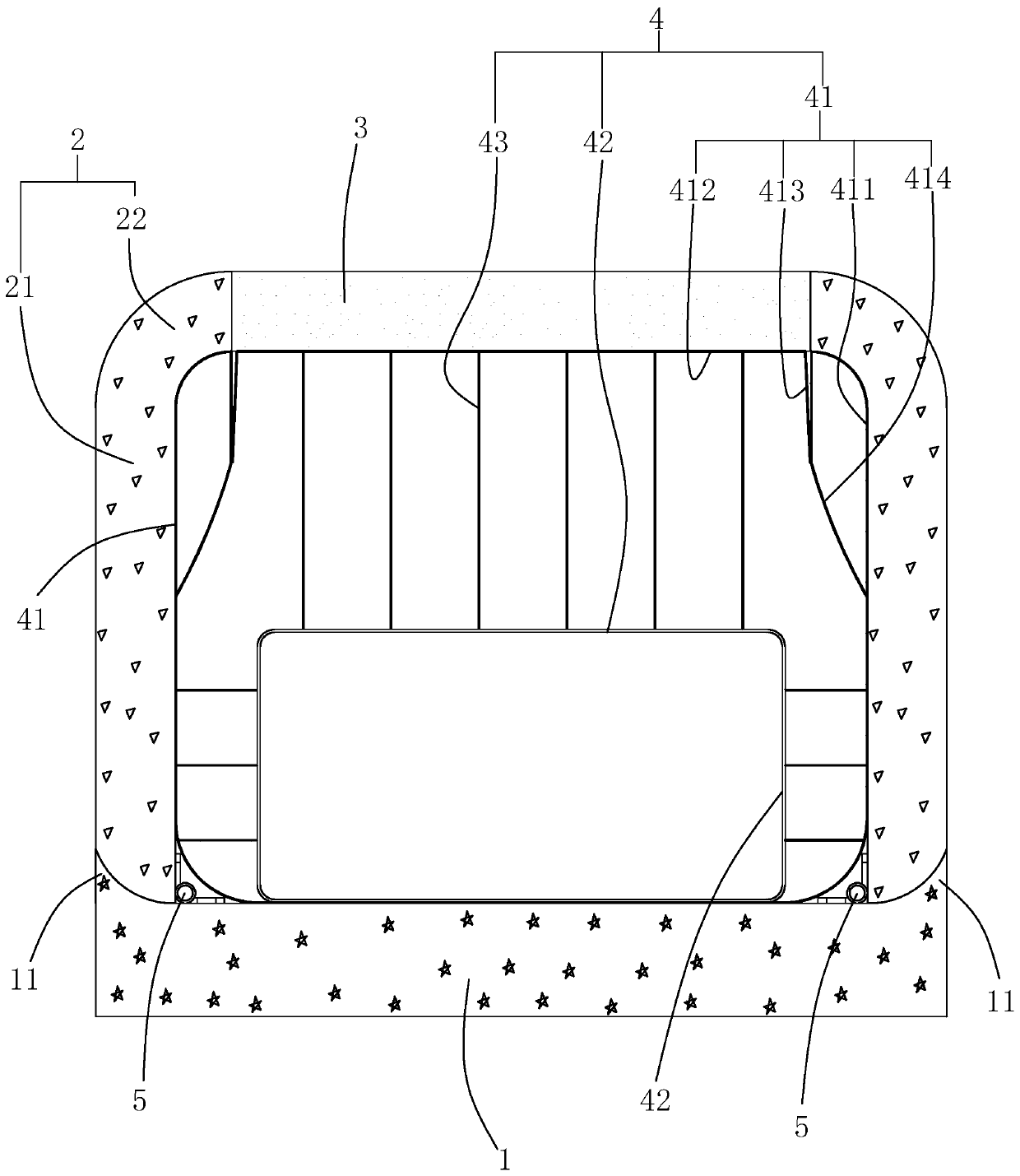
[0052] Reference figure 1 , Is a core mold for pouring a subway rail top air duct disclosed in the present invention, including a lower mold plate 1, two side mold plates hinged on both ends of the upper side of the lower mold plate 1, a supporting plate 3 located directly above the lower mold plate 1, and a The template 1, the two side templates 2 and the inflatable airbag 4 in the area enclosed by the support plate 3.

[0053] Reference figure 2 The side formwork 2 includes a side plate part 21 whose lower edge is hinged to the lower formwork 1 and a corner part 22 integrally formed on the upper edge of the side plate part 21. Specifically, the lower edge of the side plate 21 facing the inflatable airbag 4 is hinged with the lower template 1 through the hinge 5, and the side plate 21 is facing away from the inflatable airbag 4 so that the lower edge is processed with chamfered or rounded corners to Avoid scratching the rail top air duct when the side formwork 2 is separated fr...

Embodiment 2

[0060] This embodiment discloses a construction method for pouring a subway rail top air duct. The subway rail top air duct pouring uses a mandrel to perform part of the steps. The method includes the following steps:

[0061] Step 1. Set up steel pipe supports;

[0062] Step 2: Excavation of embedded steel bars;

[0063] Step 3. The integral steel reinforcement is installed to form a steel support and suspension structure for the air duct on the top of the rail;

[0064] Step 4. Mandrel installation, inflation and installation of external template of rail top air duct;

[0065] 4-1: Install the outer formwork on the underside and both sides of the rail top air duct;

[0066] 4-2: Insert the core mold into the steel supporting structure of the air duct on the top of the rail;

[0067] 4-3: Open the valve 44, connect the gas source to the gas nozzle 45 and inflate the gas into the inflatable airbag 4, and in the process of inflating the gas, manually adjust the position of the expenditure ...


PUM


Abstract

The invention relates to a core formwork used for pouring a top air passage of a subway rail. The core formwork comprises a lower formwork plate, two side formwork plates separately hinged to the twoends of the upper side of the lower formwork plate, a supporting plate located over the lower formwork plate, and an inflatable airbag. Each side formwork plate comprises a side plate part hinged to the lower formwork plate and a corner part integrally formed on the upper edge of the side plate part, wherein one edge of the corner part is connected with the side plate part, and the other edge of the corner part upwards extends towards the supporting plate and abuts against the supporting plate. The inflatable airbag comprises an outer lining. The outer lining comprises slot-shaped first liningskin and second lining skin, wherein the first lining skin is fixed between the lower formwork plate and the two side formwork plates, and only the upper side of the first lining skin is opened; thesecond lining skin is fixed to the lower side of the supporting plate, and the two edges of the second lining skin stretch out of the supporting plate; and the edge of the second lining skin is fixedly connected with the open edge of the first lining skin, so that a wrinkle which is concave towards the interior of the outer lining is formed on the outer lining and corresponds to the contact position of the supporting plate and the lower formwork plate. The core formwork has the effects of being convenient to dismantle, small in dismantling work, and capable of saving time and labor.

Description

Technical field [0001] The invention relates to the field of subway rail top air ducts, in particular to a core mold for pouring subway rail top air ducts and a construction method. Background technique [0002] In the subway station structure, the rail-top air duct is responsible for the exhaust and supply of the subway air. It is an important part of the subway station structure and directly affects the normal operation of the subway train. The cross-section of the rail-top air duct is approximately rectangular, and it is hung at the junction of the middle slab of the station and the side wall of the structure. [0003] Rail-top air ducts are divided into cast-in-place reinforced concrete rail-top air ducts and prefabricated air ducts. At present, cast-in-place method is mainly adopted in China. The construction method is to reserve air duct steel bars during the construction of the main structure of the station. After the main body is completed, the air duct on the top of the r...

Claims


Application Information

Patent Timeline
Patent Type & Authority Applications(China)
IPC IPC(8): E04G15/00E04G15/06
CPCE04G15/00E04G15/06
Inventor 徐强陈谨彭成
Owner CRPCEC SHENZHEN ENG
Why Eureka
Try Eureka