
Dehumidification dryer

A drying machine and drying barrel technology, which is applied in non-progressive drying machines, dryers, drying solid materials, etc., can solve the problems of high cost, time-consuming and laborious, complex equipment structure, etc., and achieve the effect of convenient replacement

Pending Publication Date: 2019-12-31
昆山森驰机械设备有限公司
View PDF0 Cites 0 Cited by
  • Summary
  • Abstract
  • Description
  • Claims
  • Application Information

AI Technical Summary

Problems solved by technology

[0002] Plastic particles need to be dehumidified and dried before injection molding to prevent air bubbles in the plastic products. The dehumidification devices of the existing dehumidification and drying equipment are roughly divided into two types. One is a silicone honeycomb runner. The equipment structure using this device complex, high energy consumption, and difficult miniaturization; the other is molecular sieve, the equipment using this device has simple structure, low energy consumption, and is easy to miniaturize, but because molecular sieve has strong hygroscopic ability, in order to prevent it from being exposed to the air, it usually requires The molecular sieve is injected into the container and then sealed by welding. When the molecular sieve fails and needs to be replaced, the entire container needs to be replaced, which is time-consuming, laborious and costly

Method used


Image

  • Dehumidification dryer
  • Dehumidification dryer
  • Dehumidification dryer

Examples


Embodiment Construction

[0027] The preferred embodiments of the present invention will be described in detail below in conjunction with the accompanying drawings, so that the advantages and features of the present invention can be more easily understood by those skilled in the art, so as to define the protection scope of the present invention more clearly.

[0028] The up and down directions described in the present invention refer to the attached figure 1 in the up and down direction.

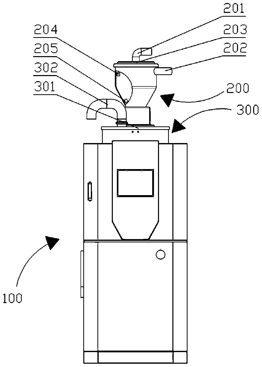
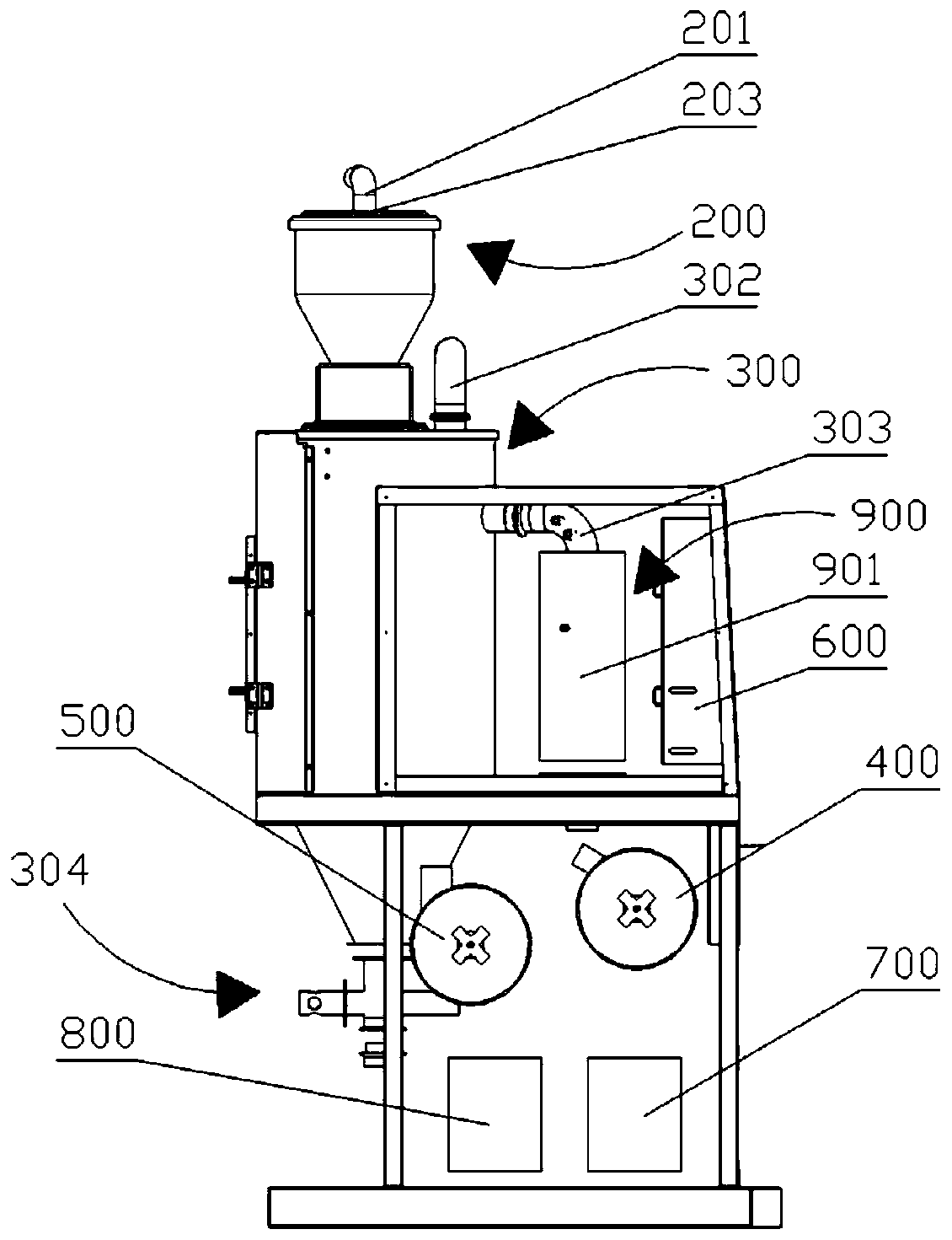
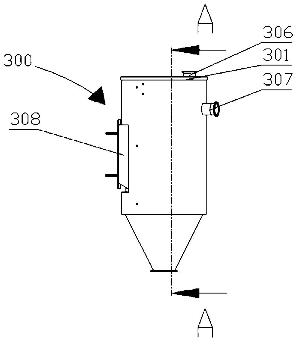
[0029] The invention provides a dehumidification dryer, such as Figure 1-2 As shown, it includes: a body 100 and a vacuum hopper 200 arranged on the body 100, a drying barrel 300, a high-precision dust filter element 400, a high-temperature resistant dust filter element 500, a dehumidification device 600, a circulation fan 700, a feeding fan 800, a heating The device 900, wherein the vacuum hopper 200 is located above the drying barrel 300, the bottom of the vacuum hopper 200 is connected to the top of the drying b...


PUM


Abstract

The invention discloses a dehumidification dryer. A tube of a dehumidification device is of a spit structure provided with a tube body, an upper cover and a lower cover; the tube body and the upper cover are detachably connected through a first hoop; the tube body and the lower cover are detachably connected through a second hoop; and sealing is performed by an upper sealing ring arranged betweenthe tube body and the upper cover and a lower sealing ring arranged between the tube body and the lower cover, so that a molecular sieve located in the tube not only can be conveniently replaced but also can keep isolated from outside air.

Description

technical field [0001] The invention relates to a dehumidification dryer. Background technique [0002] Plastic particles need to be dehumidified and dried before injection molding to prevent air bubbles in the plastic products. The dehumidification devices of the existing dehumidification and drying equipment are roughly divided into two types. One is a silicone honeycomb runner. The equipment structure using this device complex, high energy consumption, and difficult miniaturization; the other is molecular sieve, the equipment using this device has simple structure, low energy consumption, and is easy to miniaturize, but because molecular sieve has strong hygroscopic ability, in order to prevent it from being exposed to the air, it usually requires The molecular sieve is injected into the container and then sealed by welding. When the molecular sieve fails and needs to be replaced, the entire container needs to be replaced, which is time-consuming, laborious and costly. ...

Claims


Application Information

Patent Timeline
Patent Type & Authority Applications(China)
IPC IPC(8): F26B5/04F26B11/00F26B21/02F26B21/08F26B25/00F26B25/06
CPCF26B5/04F26B11/00F26B21/001F26B21/003F26B21/02F26B21/08F26B25/002F26B25/06F26B2200/08
Inventor 王承浩
Owner 昆山森驰机械设备有限公司
Features
  • Generate Ideas
  • Intellectual Property
  • Life Sciences
  • Materials
  • Tech Scout
  • Unparalleled Data Quality
  • Higher Quality Content
  • 60% Fewer Hallucinations
Learn More