Low-sidelobe lens array antenna for ETC system

A lens array, low side lobe technology, applied to antenna arrays, antennas, slot antennas and other directions that are powered on separately, can solve the problems of car following interference, reduced efficiency, active standing waves, etc., to avoid amplitude and phase errors and improve production. Efficiency, the effect of simplifying installation costs

Inactive Publication Date: 2019-12-31
XIDIAN UNIV
View PDF5 Cites 3 Cited by
  • Summary
  • Abstract
  • Description
  • Claims
  • Application Information

AI Technical Summary

Problems solved by technology

The current problem is: when the phased array scans in pitch, it will form grating lobes and side lobes of the grating lobes, which will lead to adjacent channel interference and car-following interference problems when the ETC system is working
[0003] To sum up, the problems existing in the existing technology are: traditional ETC system antennas based on linear phased arrays usually have large grating lobes and side lobes of grating lobes during scanning, resulting in the combination of digital beamforming technology The ETC drive test unit cannot accurately realize the tracking, scanning, resolution and positioning of ETC vehicles, thus reducing the speed of vehicles and the accuracy of transactions
In addition, the active standing wave of the phased array antenna during beam scanning is too high, resulting in greater system reflection loss and reduced efficiency

Method used


Image

  • Low-sidelobe lens array antenna for ETC system
  • Low-sidelobe lens array antenna for ETC system
  • Low-sidelobe lens array antenna for ETC system

Examples


Embodiment Construction

[0033] In order to make the objectives, technical solutions, and advantages of the present invention clearer and clearer, the present invention will be further described in detail below in conjunction with embodiments. It should be understood that the specific embodiments described here are only used to explain the present invention, but not to limit the present invention.

[0034] In view of the problems in the prior art, the present invention provides a low-sidelobe lens array antenna and smart terminal used in an ETC system. The present invention will be described in detail below with reference to the accompanying drawings.

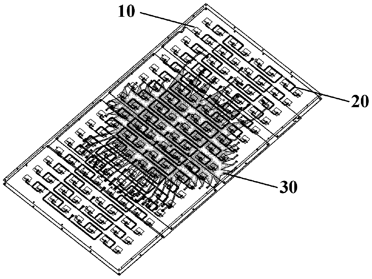
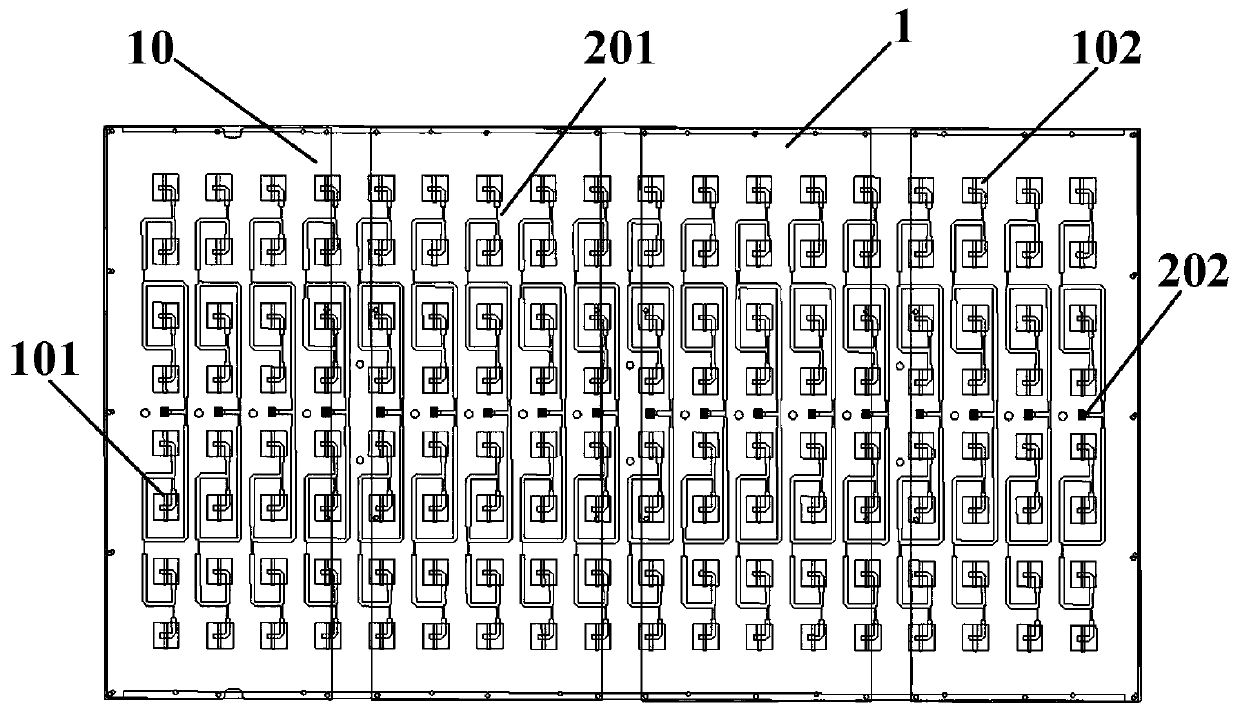
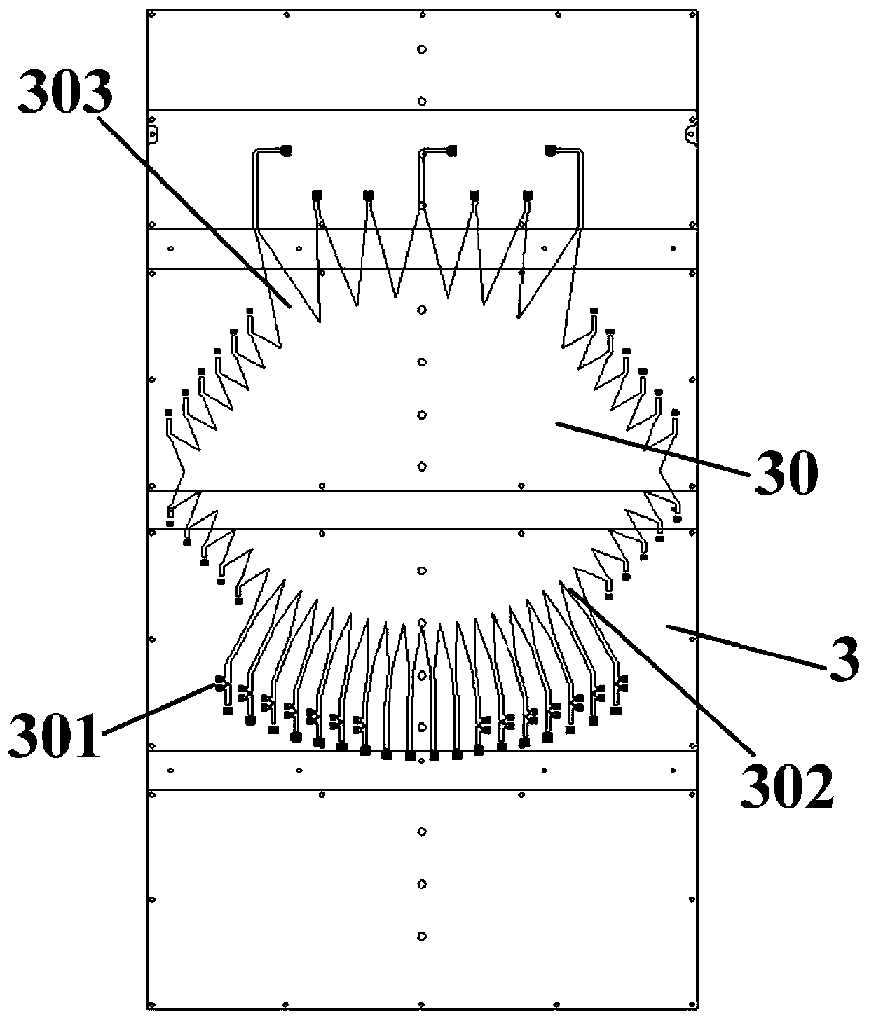
[0035] Such as Figure 1-Figure 6 As shown, the low side-lobe lens array antenna for ETC system provided by the embodiment of the present invention includes: a first dielectric substrate 1, a second dielectric substrate 2 and a third dielectric substrate 3.

[0036] The first dielectric substrate 1 is manufactured by a selective electroplating process, and an...


PUM


Abstract

The invention belongs to the technical field of antennas, and discloses a low-sidelobe lens array antenna for an ETC system. The antenna is characterized in that 8*18 microstrip loading patches are printed on a first dielectric substrate; and the upper surface of a second dielectric substrate is selectively electroplated with a microstrip line coupled feeding 8*18 slot antenna array. The microstrip line coupled feeding 8*18 slot antenna array comprises 8*18 microstrip slot antennas and 18 groups of one-to-eight unequal T-shaped power division networks; and the slot microstrip antennas generatenew resonance points by loading the microstrip patches above slots, so that the working bandwidth is broadened. A Rotman lens network is provided with seven wave beam ports and eighteen array ports;and by combining a wave beam outline, a receiving outline, phase shift microstrip lines and pi-type attenuators, signal output of equal-amplitude linear phase difference and Taylor amplitude distribution is achieved and the low-sidelobe characteristic of the pitching surface of the array antenna is obtained. The problems that a traditional ETC antenna is complex in feeding structure and large in directional diagram sidelobe interference are solved.

Description

Technical field [0001] The present invention belongs to the field of antenna technology, and particularly relates to a low sidelobe lens array antenna used in an ETC system. Background technique [0002] At present, in highways or busy bridges, tunnels and other toll places, the ETC system can allow vehicles to pass without stopping under unattended conditions, which can improve vehicle traffic efficiency, thereby improving highway traffic capacity and reducing toll management costs . Existing ETC antennas mainly use linear phased arrays to realize beam scanning on the elevation plane, and perform regional communication and identification and positioning of ETC vehicles. The communication area of ​​the ETC phased array antenna is scanned in the front and rear directions of the lane, that is, the beam is required to be scanned in the elevation direction, and the beam is fixed when the horizontal direction is possible. The current problem is that the phased array will form gratin...

Claims


Application Information

Patent Timeline
Patent Type & Authority Applications(China)
IPC IPC(8): H01Q1/38H01Q1/50H01Q13/10H01Q19/06H01Q21/00H01Q21/06G07B15/06
CPCG07B15/063H01Q1/38H01Q1/50H01Q13/106H01Q19/06H01Q21/0006H01Q21/0075H01Q21/064H01Q21/065H01Q25/008
Inventor 张志亚冯洋文帅曾凡超毛永艳张峻文
Owner XIDIAN UNIV
Why Eureka
Try Eureka