An optimization method and system for cloud load balancing

A technology of load balancing and optimization methods, applied in transmission systems, digital transmission systems, electrical components, etc., can solve the problems of long network IO paths and low efficiency, achieve flexible flow control, eliminate locks and cpu context switching, high performance The effect of cloud load balancing

Active Publication Date: 2020-07-31
GUANGZHOU BINGO SOFTWARE
View PDF6 Cites 0 Cited by
  • Summary
  • Abstract
  • Description
  • Claims
  • Application Information

AI Technical Summary

Problems solved by technology

[0007] In order to overcome the above-mentioned technical defects, the present invention provides an optimization method and system for cloud load balancing, which solves the long IO path of the traditional cloud load balancing network, as well as the low efficiency problems caused by data copying, lock overhead, CPU context switching, etc., and at the same time allows Cloud load balancing has the characteristics of flexible flow control, hot migration, elastic scaling, etc.

Method used


Image

  • An optimization method and system for cloud load balancing
  • An optimization method and system for cloud load balancing
  • An optimization method and system for cloud load balancing

Examples


Embodiment 1

[0058] This embodiment also discloses an optimization method for cloud load balance, including the steps of configuring cloud nodes, configuring virtual switches, and configuring cloud hosts. The cloud host is set in the cloud node and connected to the virtual switch.

[0059] Specifically, the configuration steps for cloud nodes are as follows: Figure 4 shown, including:

[0060] S101. Bind the network card of the cloud node to the VFIO driver.

[0061] Through this setting, when the network card receives a packet, vfio shares the address of the network packet to the user space, and when the network card sends a packet, vfio shares the address of the network packet in the user space to the network card.

[0062] S102. The network card of the cloud node starts multiple groups of first sending and receiving queues through the DPDK process.

[0063] S103, the DPDK process of the cloud node starts a plurality of first polling threads PMD, the first polling thread PMD is bound...

Embodiment 2

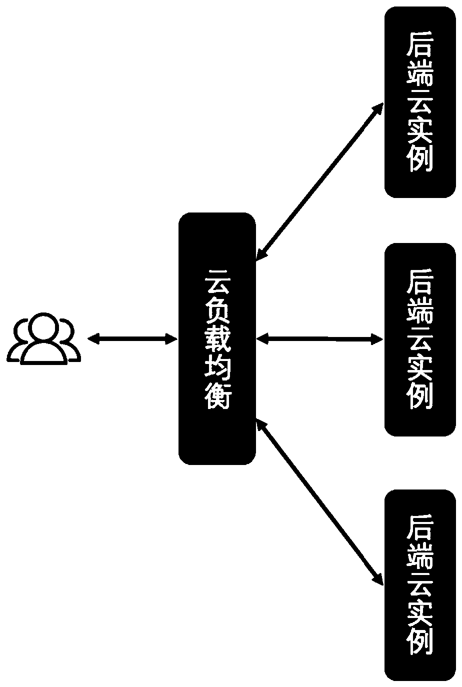
[0085] This embodiment discloses an optimization system for cloud load balancing, which includes a cloud node, a virtual switch and a cloud host: the cloud host is set in the cloud node and connected to the virtual switch.

[0086] Specifically, in this embodiment, the network card of the cloud node opens multiple sets of first sending and receiving queues through the DPDK process. The DPDK process of the cloud node starts multiple first polling threads PMD, the first polling thread PMD is bound to the first sending and receiving queue one by one, the first polling thread PMD is bound to a CPU core, the first polling thread The PMD is used to acquire the data packets in the corresponding first transceiver queue by means of active polling, and the corresponding CPU core performs transceiver processing.

[0087]The virtual switch establishes a network bridge with the datapath type of netdev, and the user mode process corresponding to the bridge is set to be bound to one or more ...


PUM


Abstract

The invention discloses an optimization method and system for cloud load balancing. By configuring parameters in cloud nodes, virtual switches, and cloud hosts respectively, network card queues of cloud nodes, polling threads of cloud nodes, and virtual switches are realized. The DPDK port queue, the vhost port queue of the virtual switch, the network card queue of the cloud host, and the load balancing service process of the cloud host correspond one by one, so that the data packets can be directly transferred between the kernel layer of the cloud node and the load balancing service process of the cloud host. Shared, polling thread and cpu binding and active polling mechanism of polling thread at the same time eliminates lock and cpu context switching , as well as low efficiency issues caused by data copying, lock overhead, CPU context switching, etc., and at the same time enable cloud load balancing to have features such as flexible flow control, hot migration, and elastic scaling. Realize high-performance cloud load balancing.

Description

technical field [0001] The invention belongs to the technical field of load balancing, and in particular relates to an optimization method and system for cloud load balancing. Background technique [0002] The cloud load balancing service is a traffic distribution control service that distributes access traffic to multiple cloud hosts at the backend according to the forwarding strategy in the cloud platform. It allows users to create cloud load balancing on the cloud platform and configure the backend of the cloud load balancing service instance, and set related load balancing policies. Its schematic diagram is as figure 1 shown. It has the characteristics of multi-tenancy, hot migration, and elastic scaling. [0003] Based on the above characteristics, the traditional implementation of cloud load balancing services is to run load balancing services in cloud hosts and provide services in a virtualized manner. The cloud network provides network access control features suc...

Claims


Application Information

Patent Timeline
Patent Type & Authority Patents(China)
IPC IPC(8): H04L29/08H04L12/24H04L12/803
CPCH04L41/0803H04L47/125H04L67/1001
Inventor 刘忻林冬艺肖兴
Owner GUANGZHOU BINGO SOFTWARE
Why Eureka
Try Eureka