High-reliable electric heating pipe sealing structure and method

A technology of sealing structure and electric heating pipe, applied in the direction of ohmic resistance waterproof/airtight, ohmic resistance heating parts, heating element shape, etc. between 4' of sealant, etc.

Pending Publication Date: 2019-12-31
GUANGZHOU JIANLONG ELECTRIC APPLIANCE
View PDF0 Cites 0 Cited by
  • Summary
  • Abstract
  • Description
  • Claims
  • Application Information

AI Technical Summary

Problems solved by technology

[0004] In actual production, if the amount of sealant 4' added during the packaging process is not enough, it is easy to create a gap between the sealing cap 3' and the sealant 4'; if the amount of glue is just right, but because the bottom of the sealing cap 3' is flat , during the pressing process of the sealing cap 3', it is easy to "hold air", and a small part of the air is "stuffed" between the sealing cap 3' and the sealant 4'; if the sealant 4' is excessively added, the sealant 4' It

Method used


Image

  • High-reliable electric heating pipe sealing structure and method
  • High-reliable electric heating pipe sealing structure and method
  • High-reliable electric heating pipe sealing structure and method

Examples


Example Embodiment

[0026] Example 1

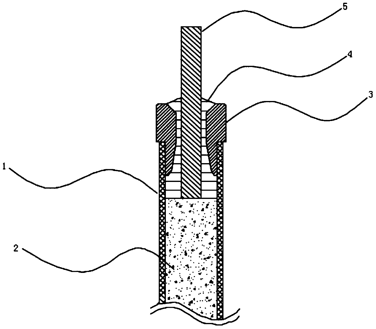
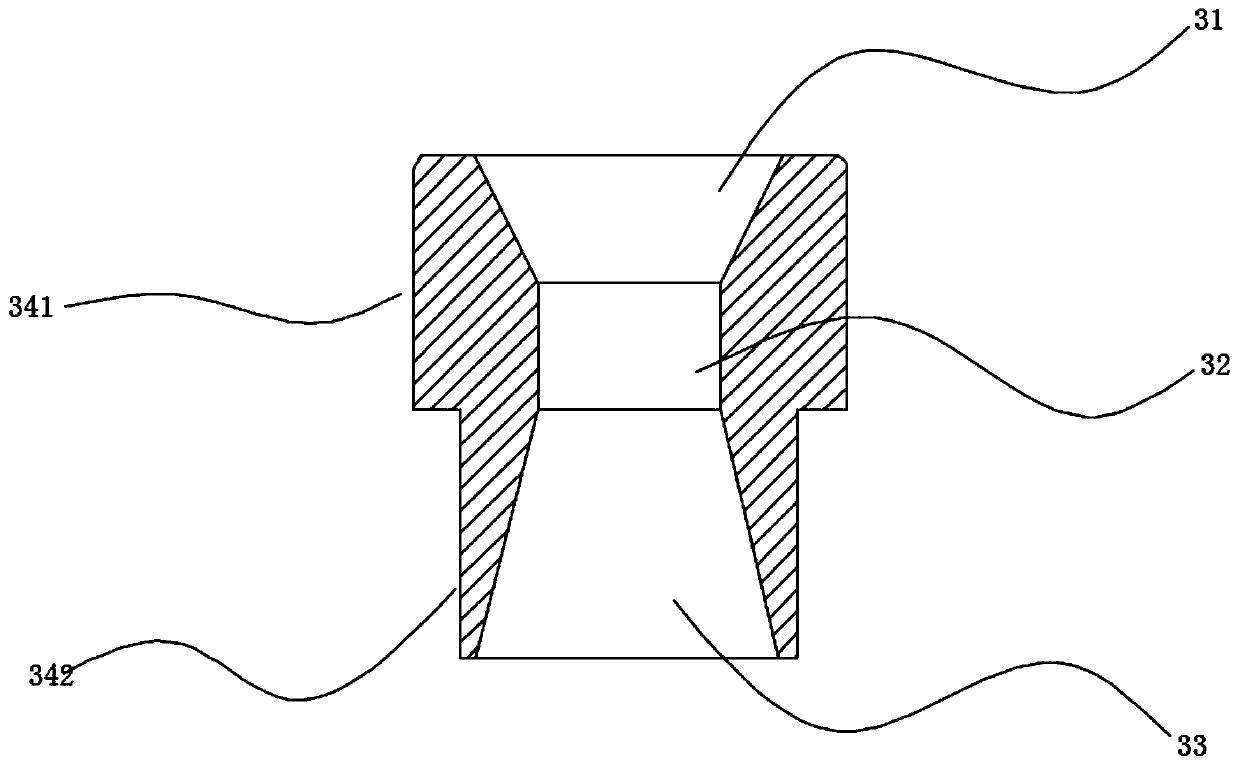
[0027] see Figure 2-Figure 3 On the one hand, the present invention provides a high-reliability electric heating pipe sealing structure, comprising an electric heating pipe body 1, a lead rod 5 is arranged in the electric heating pipe 1, and magnesium oxide powder is filled between the lead rod 5 and the electric heating pipe body 1 2. An insulating sealing device 3 is provided at the sealing portion of the electric heating tube body 1. The insulating sealing device 3 includes a sealing body, the upper end of the sealing body is provided with an upper opening 31, the lower end of the sealing body is provided with a lower opening 33, and the upper opening is 31 and the lower opening 33 are provided with a through middle channel 32, the outer side wall of the sealing body is provided with a step 34, the lead rod 5 passes through the middle channel 32 of the insulating sealing device 3, the middle channel There is a gap between 32 and the lead rod 5, and a se...

Example Embodiment

[0033] Example 2

[0034] like Figure 3-4 As shown, the difference between Embodiment 2 and Embodiment 1 is that the structure of the middle channel is different, and other structures are the same.

[0035] In this embodiment, the middle channel 32 includes a first middle channel 321 and a lower channel 322 in sequence along the upper end to the lower end of the insulating sealing device 3 . The upper end of the first middle channel 321 is communicated with the lower end of the upper opening 31 , and the first The lower end of the middle channel 321 is communicated with the upper end of the lower channel 322, and the lower end of the lower channel 322 is communicated with the upper end of the lower opening 33. The above arrangement divides the middle channel 32 into two parts, and the sealant entering the lower channel 322 passes through 4 When the middle passage 32 is formed, the lead rod and the insulating sealing device are well bonded by the sealant 4, so that the insula...

Example Embodiment

[0036] Example 3

[0037] The present invention provides a sealing method for a high-reliability electric heating tube. The sealing structure of the high-reliability electric heating tube is shown in Embodiment 1 and Embodiment 2. The sealing method includes the following steps:

[0038] 1) Fill magnesium oxide powder 2 in the electric heating tube body 1;

[0039] 2) dig out d mm of magnesium oxide powder 2 at the end of the electric heating pipe body 1;

[0040] 3) Inject the sealant 4 into the electric heating pipe body 1 in advance, and make the injected sealant 4 away from the nozzle d / 8mm of the electric heating pipe body 1; in this embodiment, d is 5-13 mm, and the above settings are easy to operate;

[0041] 4) Press the insulating sealing device 3 into the sealant 4, and the sealant 4 flows out from the gap between the intermediate channel 32 and the lead bar 5 to the upper end opening 31 to fill the gap between the sealing body and the lead bar 5.

[0042] In the ...


PUM


Abstract

A high-reliable electric heating pipe sealing structure and method are disclosed. A lead rod is arranged in an electric heating tube body. A space between the lead rod and the tube body is filled withmagnesium oxide powders. An insulation sealing device is disposed at the sealing port of the electric heating tube body and is composed of an upper opening, a middle channel, a lower channel, and a lower opening. The lead rod penetrates through the middle channel of a sealing port device. A sealant is arranged between the insulation sealing device and the electric heating pipe body. The outer diameter of the upper part of the insulation sealing device is larger than the diameter of the outer wall of the sealing port of the electric heating pipe body, and the outer diameter of the lower part of the insulation sealing device is smaller than the diameter of the inner wall of the electric heating pipe body. The diameter of the upper opening gradually decreases toward the middle of the sealingport device. The diameter of the lower channel gradually decreases toward the middle of the insulation sealing device. The lower opening is located below the lower channel. The diameter of the loweropening gradually decreases toward the lower channel. The smallest diameter of the lower opening is equal to the largest diameter of the lower channel. The high-reliable electric heating pipe sealingstructure has the advantages of good bonding during the curing process of the sealant and improving the insulation withstand voltage.

Description

technical field [0001] The invention relates to the technical field of electric heating, in particular to a high-reliability electric heating tube sealing structure and method. Background technique [0002] During the use of traditional electric heaters, the insulation resistance of the electric heating tube may decrease, resulting in damage or unusability of the electric heater. Once the above situation occurs, it will cause serious safety and quality problems. An important requirement of the electric heating tube is that there should be no moisture inside the electric heating tube. The general treatment method is to place the electric heating tube in an oven and heat it at 180-280°C for several hours to more than 10 hours, so that the moisture absorbed by the magnesium oxide powder in the electric heating tube can be fully removed. Then use RTV silica gel or epoxy resin (hereinafter collectively referred to as sealant) to seal the nozzle. [0003] Such as figure 1 As sh...

Claims


Application Information

Patent Timeline
IPC IPC(8): H05B3/04H05B3/48
CPCH05B3/04H05B3/48
Inventor 黄昊
Owner GUANGZHOU JIANLONG ELECTRIC APPLIANCE
Why Eureka
Try Eureka