
A weighing device, conveying device and method for steel rolling production

A weighing device and conveying line technology, which is applied in the field of conveying devices and weighing devices for rolling steel production, can solve the problems of increased production line area, affecting rolling quality, and prolonging billet time, so as to reduce transportation time and equipment , the effect of reducing the length

Active Publication Date: 2020-11-10
BERIS ENG & RES CORP
View PDF10 Cites 0 Cited by
  • Summary
  • Abstract
  • Description
  • Claims
  • Application Information

AI Technical Summary

Problems solved by technology

[0004] The inventor believes that between each rolling process, especially the continuous rolling production line, due to the large value of the length of the rolled piece, if a weighing element is to be installed, a conveying roller table with the same length as the piece to be measured must be installed, which will make the production line occupy a large area. The area has increased dramatically, so it is difficult to weigh individually; it can only be weighed in bundles after the product is fully rolled and formed
[0005] At the same time, the method of setting the conveying roller table and weighing elements equal to the length of the workpiece will prolong the time for the billet to enter the heating furnace and affect the rolling quality

Method used


Image

  • A weighing device, conveying device and method for steel rolling production
  • A weighing device, conveying device and method for steel rolling production

Examples


Embodiment 1

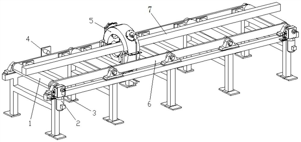
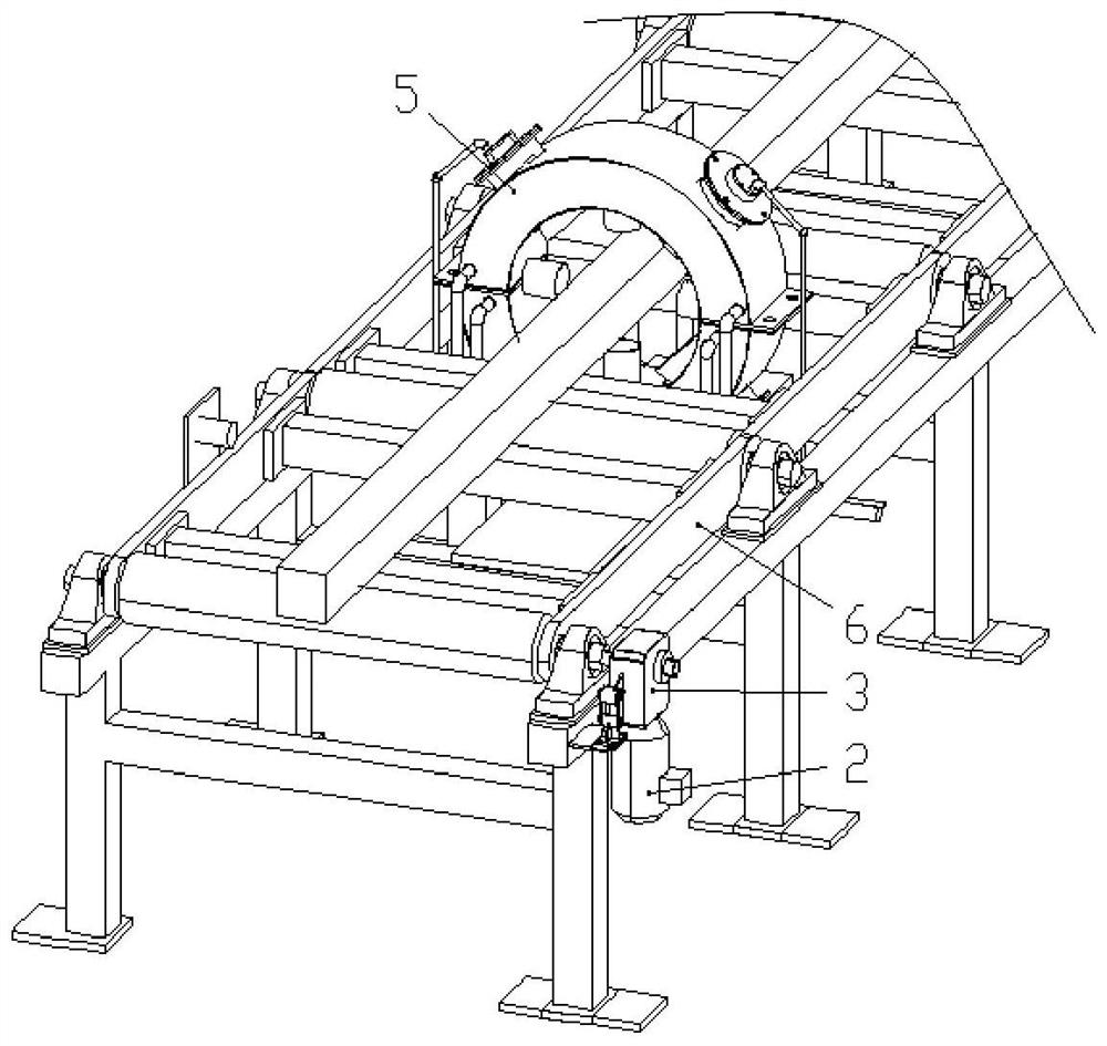
[0034] Such as Figure 1-2 As shown, this embodiment provides a weighing device for rolling steel production, including a profile scanner 5 arranged in the middle of the roller conveyor line 6, a metal detector 4 arranged on one side of the roller conveyor line 6, and a drive motor 2 A code wheel 3 coaxially arranged with the middle output shaft.

[0035] In some embodiments, the roller conveyor line 6 has a set forward direction, and the test piece 7 should reach the position of the profile scanner 5 in the roller conveyor line 6, and then reach the position of the metal detector 4, and the profile scanner The distance between 5 and the metal detector 4 should be smaller than the minimum distance of the DUT 7 .

[0036] The profile scanner 5 can allow the test piece 7 to pass and scan the cross-sectional shape of the test piece 7; the metal detector 4 can detect whether the test piece 7 arrives at the detection position of the metal detector 4; the code disc 3 can detect th...

Embodiment 2

[0046] Such as Figure 1-2 As shown, this embodiment provides a conveying device for rolling steel production, which utilizes the weighing device for rolling steel production, including a roller conveyor line 6, and the contour scanner is installed in the middle of the roller conveyor line 6 5. The metal detector 4 is provided on one side of the roller conveyor line 6, the drive roller 1 and the drive motor 2 are arranged coaxially in the roller conveyor line 6, and the output shaft of the drive motor 2 is connected to the code disc 3 Fixed connection.

Embodiment 3

[0048] This embodiment provides a weighing method for steel rolling production, which utilizes a conveying device for steel rolling production, and includes the following steps:

[0049] Place the test piece 7 with a regular shape on the upper part of the roller conveying line 6 so that the test piece 7 is transported along the conveying direction of the roller conveying line 6 .

[0050] After the front end of the DUT 7 reaches the position of the metal detector 4, the code disc 3 starts to record the angle information, and when the rear end of the DUT 7 moves away from the position of the metal detector 4, the code disc 3 stops recording the angle information, The angle information recorded by the device code disc 3 and the radius of the driving roller 1 in the roller conveyor line 6 are used to obtain the length value of the test piece 7 .

[0051] When the front end of the test piece 7 reaches the position of the metal detector 4, the weighing device controls the imaging s...


PUM


Abstract

The invention relates to a weight measuring device for steel rolling production and a conveying device and method. A length measuring device, an outline scanner and a control system are included. Theoutline scanner is arranged in the middle of a roller way conveying line and can allow a to-be-measured part to get through and scan the section shape of the to-be-measured part. The length measuringdevice comprises a metal detector arranged on one side of the roller way conveying line. The metal detector can detect whether the to-be-measured part reaches a detection position of the metal detector. The length measuring device further comprises a coded disc coaxial with an output shaft of a driving motor. The coded disc can detect the rotation angle of the output shaft of the driving motor. According to the weight measuring device for steel rolling production and the conveying device and method, the arrangement of a conveying roller way equal to the to-be-measured part in length and a weight measuring element can be avoided, the staying time of the to-be-measured part on the roller way is reduced, the influence on rolling quality is avoided, and the weight of the to-be-measured part with a large length numerical value can be measured.

Description

technical field [0001] The invention belongs to the technical field of weighing devices, and in particular relates to a weighing device, a conveying device and a method for steel rolling production. Background technique [0002] In steel rolling production, the finished product rate has always been a key indicator for each production plant to measure and improve economic benefits. However, due to the limitation of the weighing method, generally only the weight measurement of the blank and the finished product is carried out. Billet weighing generally chooses to set a section of roller table suitable for the length of the billet in front of the heating furnace, and set weighing elements at the roller table for weighing. [0003] With the development of bar, wire rod and section steel production technology, direct rolling and endless rolling have begun to be applied to actual production, which has improved the yield of rolling line and become the process adopted by new produc...

Claims


Application Information

Patent Timeline
Patent Type & Authority Patents(China)
IPC IPC(8): B21B38/00B21B39/02
CPCB21B38/00B21B39/02B21B2261/18
Inventor 李强于玲赵栋郭泓娇
Owner BERIS ENG & RES CORP
Learn More