Automatic clamp for external holding positioning and end face pressing for thin-wall sleeve

A technology of thin-wall sleeves and end faces, which is applied in the field of fixtures and fixtures, can solve problems such as clamping deformation of thin-wall sleeves, and achieve the effects of solving clamping deformation, high work efficiency, and simple structure

Pending Publication Date: 2020-01-03
合肥波林新材料股份有限公司
View PDF0 Cites 1 Cited by
  • Summary
  • Abstract
  • Description
  • Claims
  • Application Information

AI Technical Summary

Problems solved by technology

[0003] The present invention designs an automatic clamp that can realize external hugging and pressing the end face at the same time, which solves the problem of clamping deformation of the thin-walled sleeve

Method used


Image

  • Automatic clamp for external holding positioning and end face pressing for thin-wall sleeve
  • Automatic clamp for external holding positioning and end face pressing for thin-wall sleeve
  • Automatic clamp for external holding positioning and end face pressing for thin-wall sleeve

Examples


Embodiment Construction

[0017] The technical solutions in the embodiments of the present invention will be clearly and completely described below in conjunction with the accompanying drawings. Apparently, the described embodiments are only some, not all, embodiments of the present invention. Based on the embodiments of the present invention, all other embodiments obtained by persons of ordinary skill in the art without making creative efforts belong to the protection scope of the present invention.

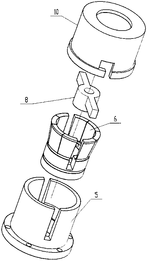
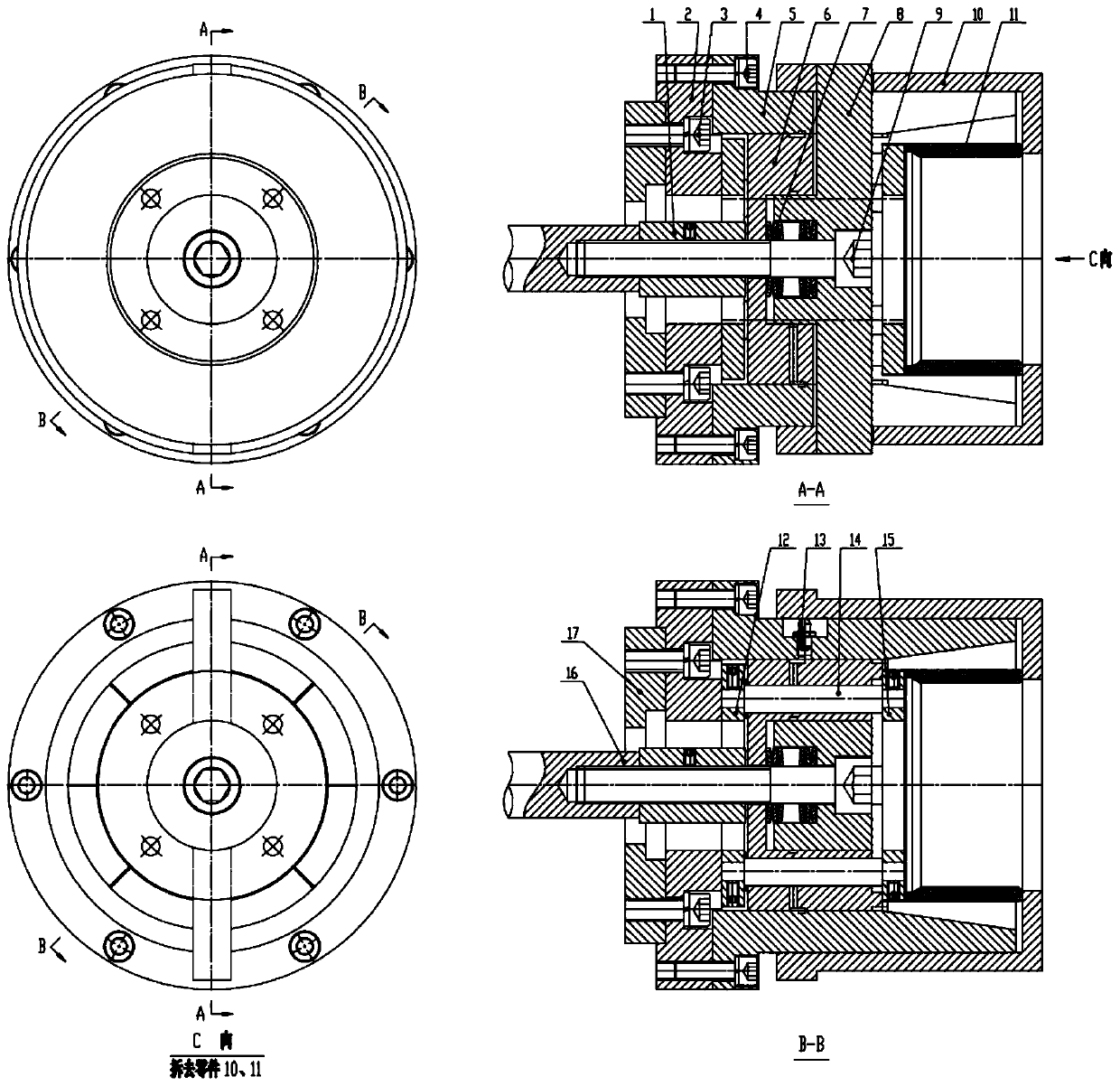
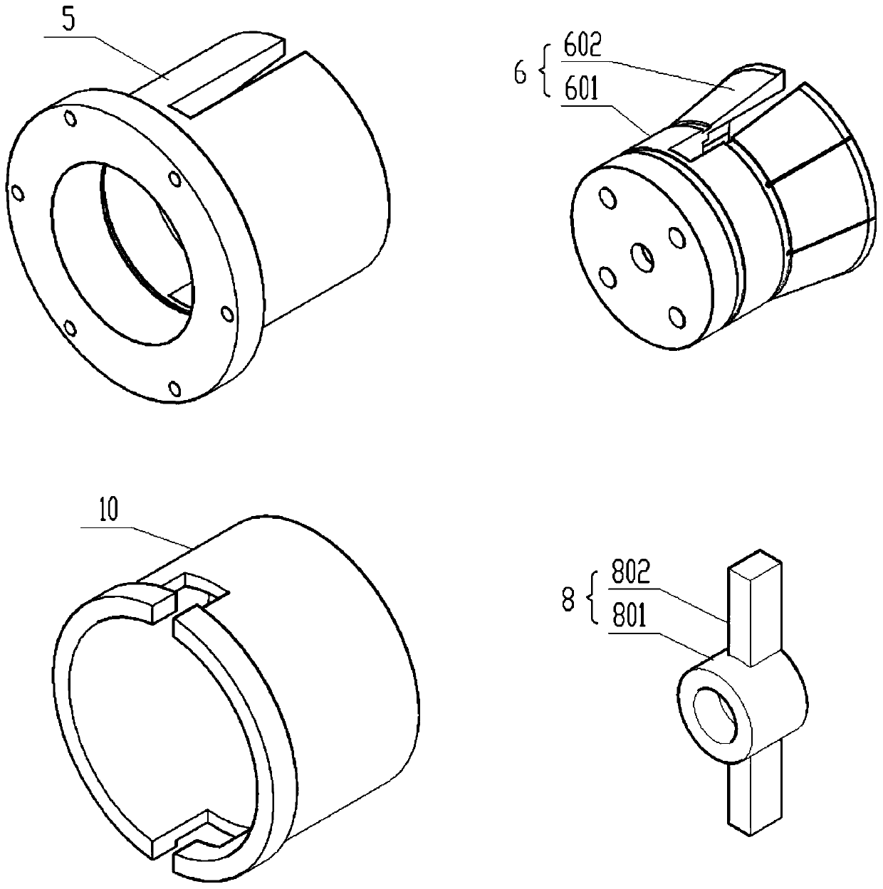
[0018] see figure 1 , figure 2 , image 3 In this embodiment, the structural form of the automatic fixture that is positioned outside the thin-walled sleeve and pressed against the end face is: the transition flange 2 is installed on the flange of the machine tool spindle with screw one 3; the clamp body 5 passes through the seam with screw two 4 Installed on the end face of the transition flange 2, the clamp body 5 has a round hole on the left end, an inner taper hole on the right end, and a radially...


PUM


Abstract

The invention provides an automatic clamp for external holding positioning and end face pressing for a thin-wall sleeve, and belongs to the field of machining. According to the automatic clamp, a clamp body is arranged on a transition flange, the left end of the clamp body is provided with a circular hole, and the right end of the clamp body is provided with a conical hole; an external holding elastic sleeve is concentrically arranged in the clamp body, the left end of the external holding elastic sleeve is matched with the circular hole of the clamp body, and the right end of the external holding elastic sleeve and the conical hole of the clamp body form a conical surface holding-tightly structure; a column body of a pressing rod is matched with an inner hole at the left end of the external holding elastic sleeve, a disc spring is arranged between the column body of the pressing rod and the inner hole at the left end of the external holding elastic sleeve, a rod body of the pressing rod extends out of the clamp body through a through rectangular groove in the external holding elastic sleeve and the clamp body, and the pressing rod is connected with a machine tool pull rod throughusing a screw; an end face pressing sleeve concentrically sleeves on the clamp body, and L-shaped through grooves on the pressing sleeve is buckled with the rod body of the pressing rod; an internal supporting ring, an external supporting ring and supporting rods form a frame to sleeve on the two sides of the external holding elastic sleeve and the pressing rod; and the thin-wall sleeve is placedin an inner hole of the right end of the external holding elastic sleeve, and is axially positioned by the external supporting ring, the external holding elastic sleeve holds the thin-wall sleeve by the pressing rod through the disc spring, the end face of the thin-wall sleeve is pressed by the end face pressing sleeve at the same time, and the problem of clamping deformation of the thin-wall sleeve is solved.

Description

technical field [0001] The invention relates to a tooling fixture in the mechanical processing industry, more specifically to an automatic fixture for a thin-walled sleeve used in an automatic lathe for positioning and pressing the end face. Background technique [0002] When an automatic lathe processes the inner hole of a thin-walled sleeve, clamping deformation is a difficult problem to solve. At this time, it is generally not possible to use a power chuck to clamp, and it is necessary to use an externally-embracing elastic clamp or a pressure-end clamp. Due to the small rigidity of the thin-walled sleeve, the existing externally embracing elastic clamps will still cause radial clamping deformation of the thin-walled sleeve, which will affect the machining accuracy; the machining accuracy of the end clamp depends on the radial direction of the thin-walled sleeve on the fixture Positioning accuracy, but to install and take out the thin-walled sleeve on the fixture, there ...

Claims


Application Information

Patent Timeline
Patent Type & Authority Applications(China)
IPC IPC(8): B23Q3/12B23B31/40
CPCB23B31/402B23B31/4053B23Q3/12
Inventor 房卫东韦仑长张俊杰任刚强
Owner 合肥波林新材料股份有限公司
Why Eureka
Try Eureka