
Automatic discharging device for combined foot pad injection mold

A technology of automatic discharge device and injection mold, applied in the direction of coating, etc., can solve the problems of time-consuming, affecting production efficiency, and large number of foot pads, so as to improve production efficiency and shorten the time for taking materials.

Inactive Publication Date: 2020-01-03
东莞市嘉宏机电科技有限公司
View PDF6 Cites 1 Cited by
  • Summary
  • Abstract
  • Description
  • Claims
  • Application Information

AI Technical Summary

Problems solved by technology

[0002] Machine tool foot pads, also called machine tool pads, are support blocks installed on machine feet. Machine tool pads can adjust the height of the machine tool. Existing machine tool pads are generally composed of studs and pads. Rigid materials are used. In order to achieve effective shock absorption, a layer of rubber pad is usually covered on the pad, and the rubber pad usually flows liquid rubber around the pad through injection molding equipment, and it is formed after the rubber cools and solidifies. Combined machine tool feet, and for small machine tool feet, multiple foot pads can be injected in one injection mold at the same time. When taking materials, one needs to take the foot pads out of the injection mold. It takes a lot of time and affects production efficiency

Method used


Image

  • Automatic discharging device for combined foot pad injection mold
  • Automatic discharging device for combined foot pad injection mold
  • Automatic discharging device for combined foot pad injection mold

Examples


Embodiment Construction

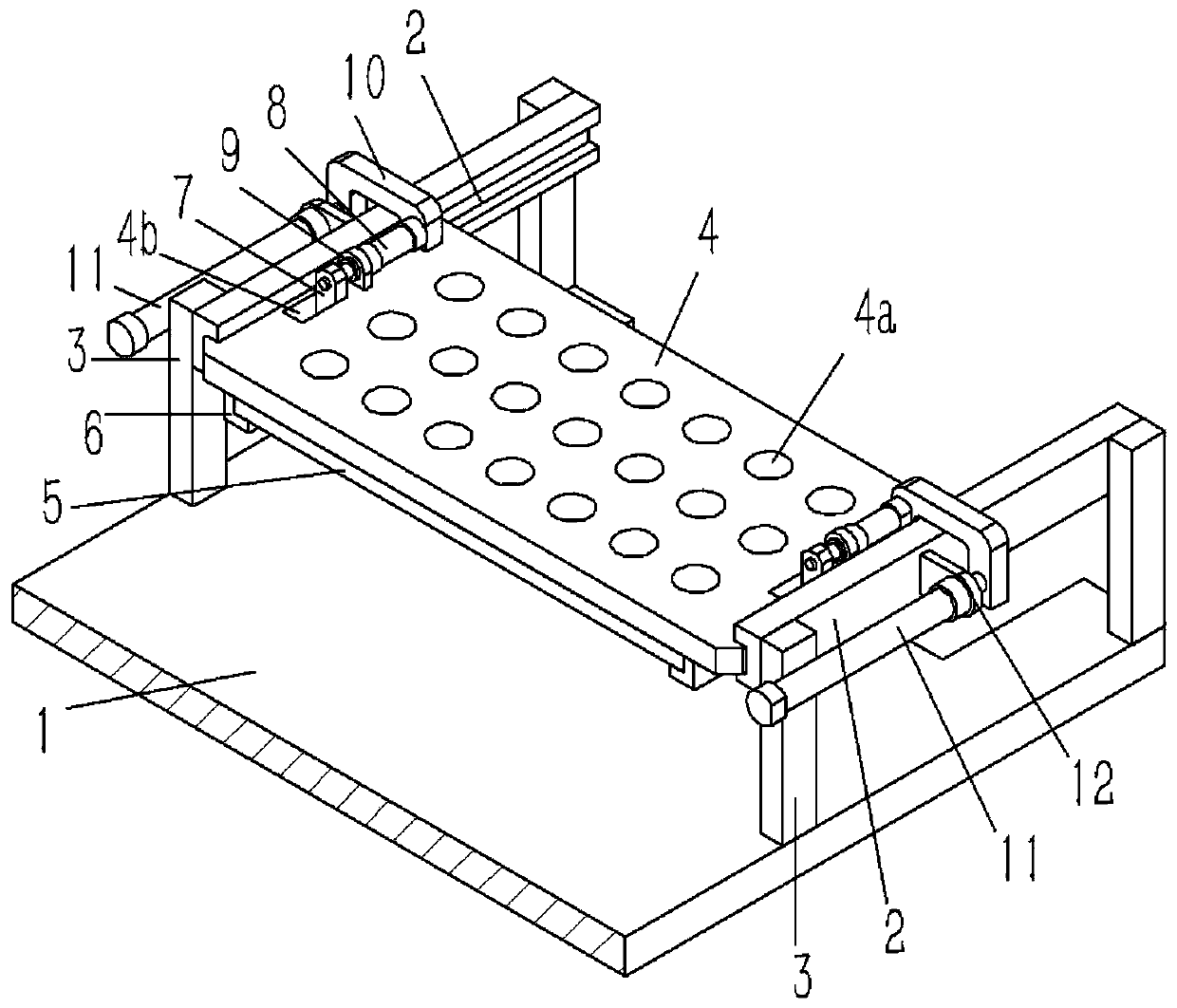
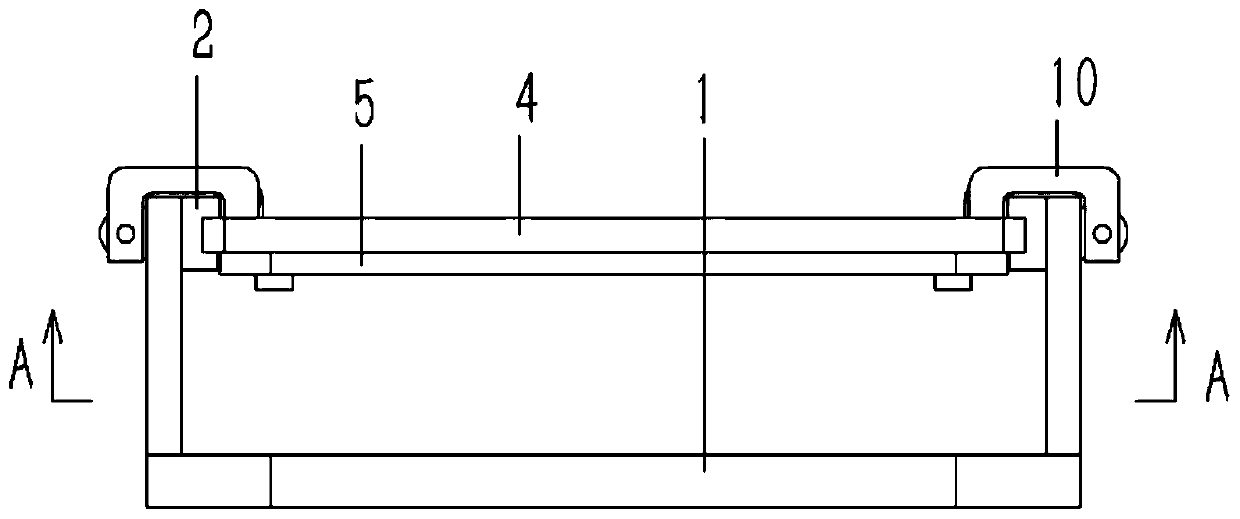
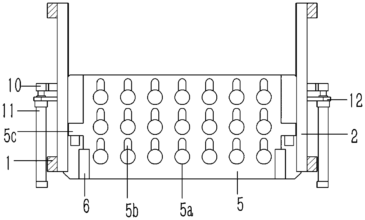
[0019] Example: see Figures 1 to 4 As shown, an automatic discharge device for a combined foot pad injection mold includes a conveying platform 1 of the injection mold, the conveying platform 1 is provided with a lower mold of the foot pad mold, and the two sides of the lower mold are arranged on longitudinal groove rails 2, The front and rear ends of the groove rail 2 are fixed with columns 3, and the lower ends of the columns 3 are fixed on the conveying platform 1. The upper side of the lower mold is provided with a horizontal positioning plate 4, and several positioning holes 4a are formed on the positioning plate 4 for positioning. Both sides of the plate 4 are inserted in the channel of the groove rail 2; the lower end surface of the positioning plate 4 is against the clamping plate 5, and the clamping plate 5 is formed with a plurality of through holes 5a opposite to the positioning holes 4a, and the through holes 5a A card slot 5b extending backward is formed on the i...


PUM


Abstract

The invention discloses an automatic discharging device for a combined foot pad injection mold. The automatic discharging device comprises a conveying platform of the injection mold. A lower mold of afoot pad mold is arranged on the conveying platform, longitudinal grooved rails are arranged on two sides of the lower mold, columns are fixed to the front and back ends of each grooved rail, the lower ends of the columns are fixed to the conveying platform, a horizontal positioning plate is arranged on the upper side of the lower mold, a plurality of positioning holes are formed in the positioning plate, and two sides of the positioning plate are inserted into the channels of the grooved rails; a clamping plate leans against the lower end surface of the positioning plate, a plurality of through holes opposite to the positioning holes are formed in the clamping plate, slots extending backward are formed in the inner walls of the back ends of the through holes, two sides of the front end of the clamping plate are inserted to a guide block, and the guide block is fixed to the lower end surface of the positioning plate. The automatic discharging device can automatically reclaim from theinjection mold at one time to shorten the reclaiming time, so that the production efficiency is improved.

Description

technical field [0001] The invention relates to the technical field of injection molds, and more specifically relates to an automatic discharge device of an injection mold for a combined foot pad. Background technique [0002] Machine tool foot pads, also called machine tool pads, are support blocks installed on machine feet. Machine tool pads can adjust the height of the machine tool. Existing machine tool pads are generally composed of studs and pads. Rigid materials are used. In order to achieve effective shock absorption, a layer of rubber pad is usually covered on the pad, and the rubber pad usually flows liquid rubber around the pad through injection molding equipment, and it is formed after the rubber cools and solidifies. Combined machine tool feet, and for small machine tool feet, multiple foot pads can be injected in one injection mold at the same time. When taking materials, one needs to take the foot pads out of the injection mold. It takes a lot of time and aff...

Claims


Application Information

Patent Timeline
Patent Type & Authority Applications(China)
IPC IPC(8): B29C45/42B29C45/14
CPCB29C45/14819B29C45/42B29C45/4225
Inventor 陈文清
Owner 东莞市嘉宏机电科技有限公司
Learn More