Eureka AIR delivers breakthrough ideas for toughest innovation challenges, trusted by R&D personnel around the world.

Steel pipe pile assembly, foundation pit retaining structure and construction method of foundation pit retaining structure

A technology for foundation pit enclosure and steel pipe piles, which is applied in basic structure engineering, excavation, sheet pile wall and other directions, can solve problems such as hole reaming, pile position deviation, and insignificant soil squeeze effect, and achieves simple construction process, The effect of reducing construction noise and construction waste, and high construction efficiency

Pending Publication Date: 2020-01-03
SHANGHAI NO 4 CONSTR
View PDF4 Cites 5 Cited by
  • Summary
  • Abstract
  • Description
  • Claims
  • Application Information

AI Technical Summary

Problems solved by technology

[0002] At present, the design of deep foundation pit enclosure structure mostly adopts the traditional enclosure system. The main enclosure systems include the following two types: 1) Bored pile + water-stop curtain enclosure system. At the same time, there are quality hidden dangers such as hole expansion and pile position offset; 2) Steel pipe piles + water-stop curtain enclosure system, steel pipe piles have the advantages of thin-walled driving and no obvious soil squeezing effect, but in essence It still belongs to the separated pile enclosure structure, and a water-stop curtain needs to be arranged outside the pit

Method used


Image

  • Steel pipe pile assembly, foundation pit retaining structure and construction method of foundation pit retaining structure
  • Steel pipe pile assembly, foundation pit retaining structure and construction method of foundation pit retaining structure
  • Steel pipe pile assembly, foundation pit retaining structure and construction method of foundation pit retaining structure

Examples


Embodiment Construction

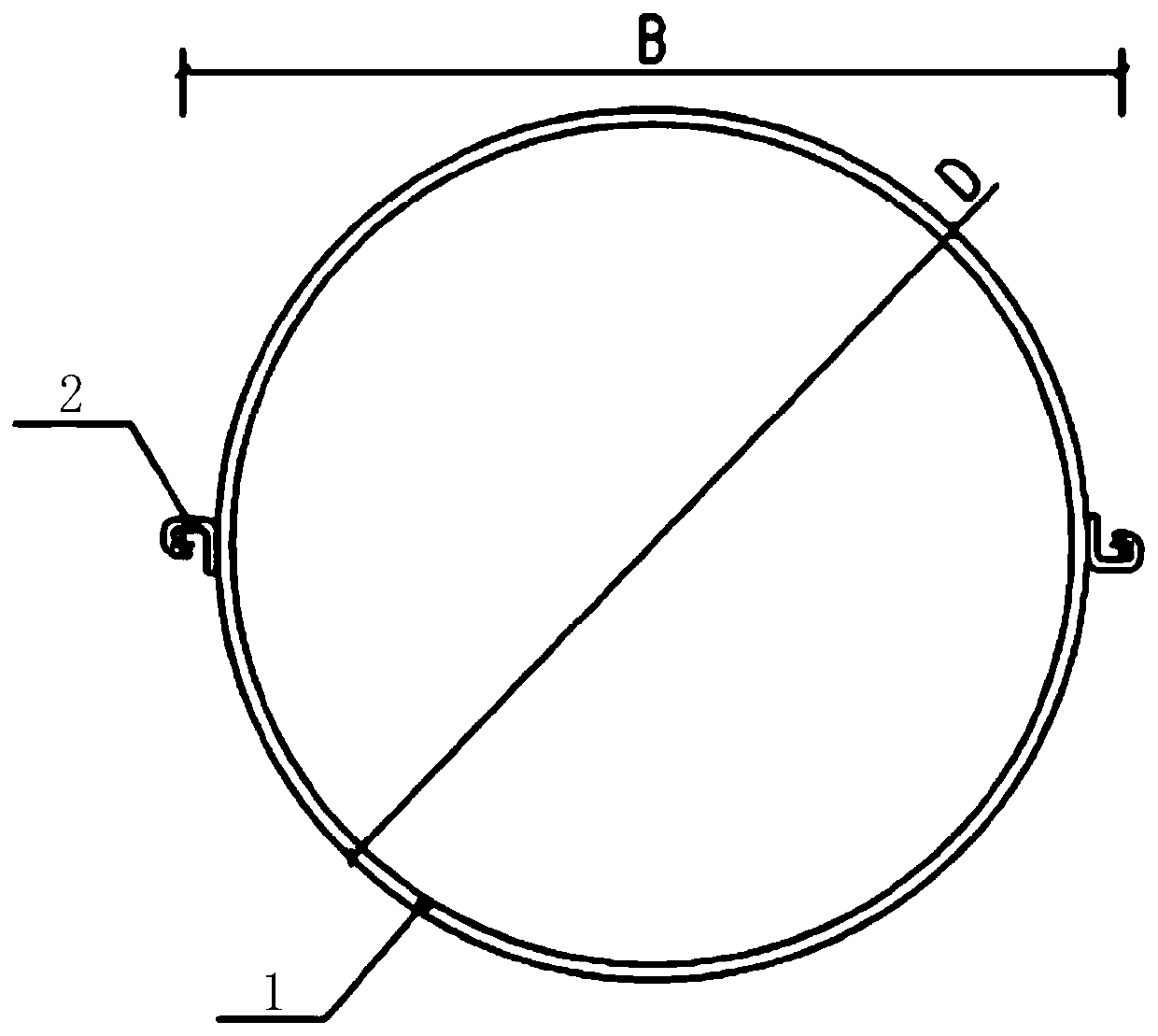
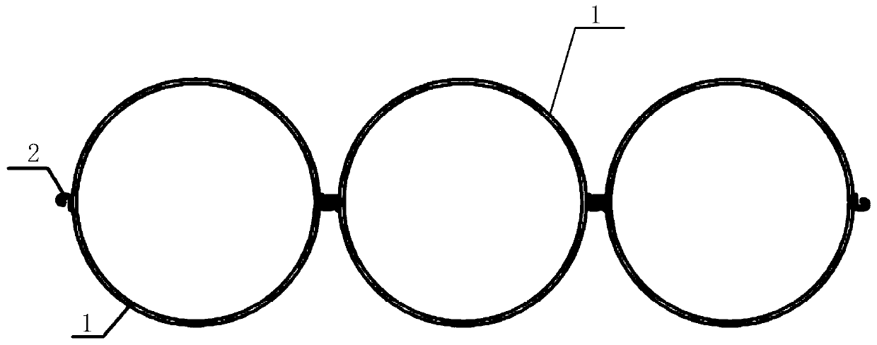
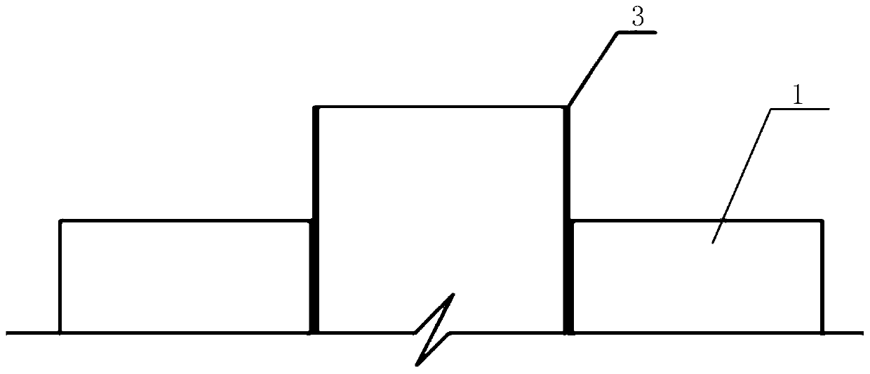
[0028] The steel pipe pile assembly, foundation pit enclosure structure and construction method proposed by the present invention will be further described in detail below in conjunction with the accompanying drawings and specific embodiments. Advantages and features of the present invention will be apparent from the following description and claims. It should be noted that all the drawings are in a very simplified form and use imprecise scales, and are only used to facilitate and clearly assist the purpose of illustrating the embodiments of the present invention.

[0029] Please refer to figure 2 , which is a top view of the steel pipe pile assembly in an embodiment of the present invention. Such as figure 2 As shown, the steel pipe pile assembly includes: at least two steel pipe piles 1 arranged side by side and lock pairs matched with the steel pipe piles 1; wherein, two locks 2 in each lock pair are opposite to its The supporting steel pipe piles 1 are arranged in an ...


PUM


Abstract

The invention provides a steel pipe pile assembly and a foundation pit retaining structure. The steel pipe pile assembly comprises at least two steel pipe piles arranged in parallel and lock hook pairs matched with the steel pipe piles, wherein two lock hooks in each lock hook pair are distributed in axial symmetry relative to the matched steel pipe piles; the lock hooks of the two adjacent steelpipe piles are bitten for sealing, so that the two steel pipe piles are integrally connected and the gap between the two steel pipe piles is sealed. Foundation pit retaining is implemented through theabove steel pipe pile assembly to form the integrated steel pipe pile enclosure system integrating soil retaining and permeability resistance properties based on the good properties of high strength,high stiffness and high stability of the steel pipe pile assembly. In the pile sinking process, the steel pipe piles have the advantages of thin-wall driving and not obvious soil compaction effect. Moreover, the construction procedures are simple, and the construction efficiency is high. The steel pipe piles can be connected through the lock hooks. There is no need to arrange a waterproof curtainon the outside of a pit. The construction noise and construction waste are reduced. The steel pipe pile, the foundation pit retaining structure and the construction method of the foundation pit retaining structure are consistent with green construction.

Description

technical field [0001] The invention relates to the technical field of enclosure system construction, in particular to a steel pipe pile assembly, a foundation pit enclosure structure, and a construction method for the foundation pit enclosure structure. Background technique [0002] At present, the design of deep foundation pit enclosure structure mostly adopts the traditional enclosure system. The main enclosure systems include the following two types: 1) Bored pile + water-stop curtain enclosure system. At the same time, there are quality hidden dangers such as hole expansion and pile position offset; 2) Steel pipe piles + water-stop curtain enclosure system, steel pipe piles have the advantages of thin-walled driving and no obvious soil squeezing effect, but in essence It still belongs to the separated pile row enclosure structure, and a water-stop curtain needs to be arranged outside the pit. [0003] Therefore, how to retain the advantages of the traditional enclosure...

Claims


Application Information

Patent Timeline
Patent Type & Authority Applications(China)
IPC IPC(8): E02D5/28E02D17/04
CPCE02D5/285E02D17/04
Inventor 胡哲彬唐建成严佳梁张云妹陈方刘天石汤天鸣吴杰郑晏华
Owner SHANGHAI NO 4 CONSTR
Why Eureka
Eureka Blog
Learn More