
Upper flange component and compressor

A component and flange technology, which is applied in the field of upper flange components and compressors, can solve problems such as adverse effects of heat exchangers and affect the performance of air conditioning systems, and achieve the effect of avoiding oil volume decline and reducing oil output.

Pending Publication Date: 2020-01-03
ZHUHAI LANDA COMPRESSOR +1
View PDF0 Cites 2 Cited by
  • Summary
  • Abstract
  • Description
  • Claims
  • Application Information

AI Technical Summary

Problems solved by technology

[0003] However, during the operation of the rotary compressor in the prior art, a large amount of lubricating oil is carried into the upper space of the compression mechanism by the refrigerant airflow, and is discharged from the compressor with the refrigerant, forming an oil discharge volume (during the operation of the hermetic rotary compressor, A large amount of refrigeration oil is carried by the refrigerant airflow into the upper space of the motor, where separation occurs, and the separated lubricating oil flows back down along the gap between the housing and the motor, and the unseparated tiny oil droplets are discharged with the refrigerant airflow Compressor, forming oil discharge), forming an oil film on the surface of the heat exchanger, which will have a negative impact on the heat exchanger of the air conditioner and affect the performance of the air conditioning system

Method used


Image

  • Upper flange component and compressor
  • Upper flange component and compressor
  • Upper flange component and compressor

Examples


Embodiment 1

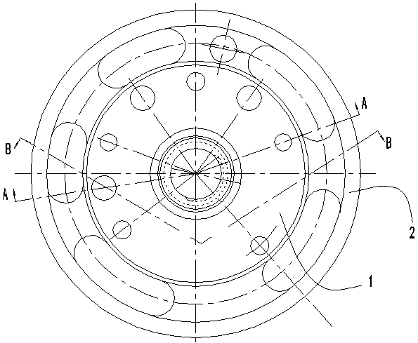
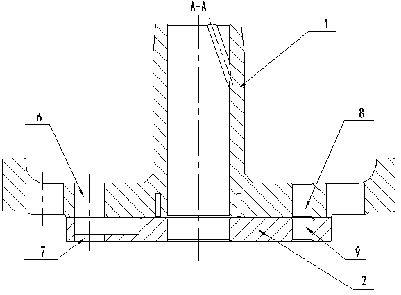
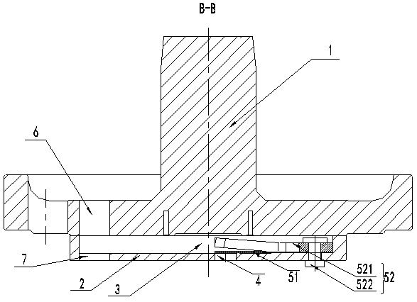
[0026] Such as Figure 1-3 As shown, an upper flange assembly includes a bearing 1 and an exhaust baffle 2, the exhaust baffle 2 is bolted to the lower end of the bearing 1, an air flow channel 3 is opened on the exhaust baffle 2, and the lower end of the air flow channel 3 There is an exhaust hole 4 communicating with the airflow channel 3, and an exhaust valve assembly 5 for controlling the opening and closing of the exhaust hole 4 is fixed in the airflow channel 3, and a bearing exhaust channel 6 communicating with the airflow channel 3 is opened on the bearing 1 The end of the exhaust partition 2 away from the exhaust hole 4 is also provided with a partition exhaust passage 7 communicating with the air flow passage 3 . When the compressor is working, after the high-pressure chamber reaches the exhaust pressure, the exhaust valve assembly 5 is squeezed open by the pressure, so that the oil-air mixture is discharged through the exhaust hole 4, and then the through-flow air p...

Embodiment 2

[0034] Such as Figure 6 As shown, the difference between the present embodiment and the first embodiment is that the air flow passage 3 is inclined to the axis line of the exhaust partition 3, and at the same time, there is a The small hole 17 communicates with the air flow channel.

[0035] The advantage of this embodiment is that the channel wall of the airflow channel 3 can be inclined, so that the refrigerated oil can flow into the oil pool from the exhaust hole 4 and the small hole along the airflow channel 3 .

[0036] The beneficial effects of the present invention are as follows: due to the arrangement of bearings and exhaust baffles, when the compressor is working, after the high-pressure chamber reaches the exhaust pressure, the exhaust valve assembly is squeezed and opened by the pressure, so that the oil-gas mixture passes through the exhaust hole It is discharged, and then discharged from the bearing exhaust passage to the upper cavity of the compression mechani...


PUM


Abstract

The invention provides an upper flange component. The upper flange component comprises a bearing and an exhausting partition plate; the exhausting partition plate is fixed to the lower end of the bearing and is provided with an air flow passage; the lower end of the air flow passage is provided with an exhaust vent which communicates with the air flow passage; an exhaust valve component used for controlling the opening and closing of the exhaust vent is fixedly arranged inside the air flow passage; the bearing is provided with a bearing exhaust passage which communicates with the air flow passage; and the end, far away from the exhaust vent, of the exhausting partition plate is further provided with a partition plate exhaust passage which communicates with the air flow passage. The upper flange component can reduce the oil output of the compressor in order to prevent the problem about compressor faults caused by reduction of oil amount inside the compressor and deficiency of oil supplypumpage, can also prevent refrigerant oil from entering a system so that oil films are not formed on the surface of a heat exchanger and reduces adverse effects generated on the heat exchanger of anair conditioner so that the performances of an air conditioning system are not affected.

Description

technical field [0001] The invention relates to the technical field of compressors, in particular to an upper flange assembly and a compressor. Background technique [0002] A compressor is a driven fluid machine that elevates low-pressure gas to high-pressure gas, and is the heart of the refrigeration system. It inhales low-temperature and low-pressure refrigerant gas from the suction pipe, drives the piston to compress it through the operation of the motor, and discharges high-temperature and high-pressure refrigerant gas to the exhaust pipe to provide power for the refrigeration cycle; thus realizing compression → condensation (heat release )→expansion→evaporation (endothermic) refrigeration cycle. Compressors are divided into piston compressors, screw compressors, centrifugal compressors, linear compressors, etc. The entry introduces the working principle, classification, accessories, specifications, operation requirements, production of compressors, common faults and ...

Claims


Application Information

Patent Timeline
Patent Type & Authority Applications(China)
IPC IPC(8): F04C29/12F04C29/02
CPCF04C29/026F04C29/128
Inventor 侯平朱伟丁学超
Owner ZHUHAI LANDA COMPRESSOR
Learn More