
Raman spectrum scanning imaging system based on SPP thermoelectric optical tweezers

A technology of Raman spectroscopy and scanning imaging, which is applied in the field of Raman spectroscopy scanning imaging system, can solve the problem of stable capture of difficult nanometer particles

Inactive Publication Date: 2020-01-03
SHENZHEN UNIV
View PDF2 Cites 3 Cited by
  • Summary
  • Abstract
  • Description
  • Claims
  • Application Information

AI Technical Summary

Problems solved by technology

[0004] However, whether it is laser or SPP optical tweezers technology, thermal effects are unavoidable, and the convection, gradient, etc. generated by thermal effects will affect the stability of optical tweezers capture, and it is difficult for the existing technology to achieve the stability of nano-scale particles. Capture and perform Raman spectral scanning imaging under SPP field enhancement to realize dynamic Raman spectral scanning imaging within the range of the sample to be tested

Method used


Image

  • Raman spectrum scanning imaging system based on SPP thermoelectric optical tweezers
  • Raman spectrum scanning imaging system based on SPP thermoelectric optical tweezers

Examples


Embodiment 1

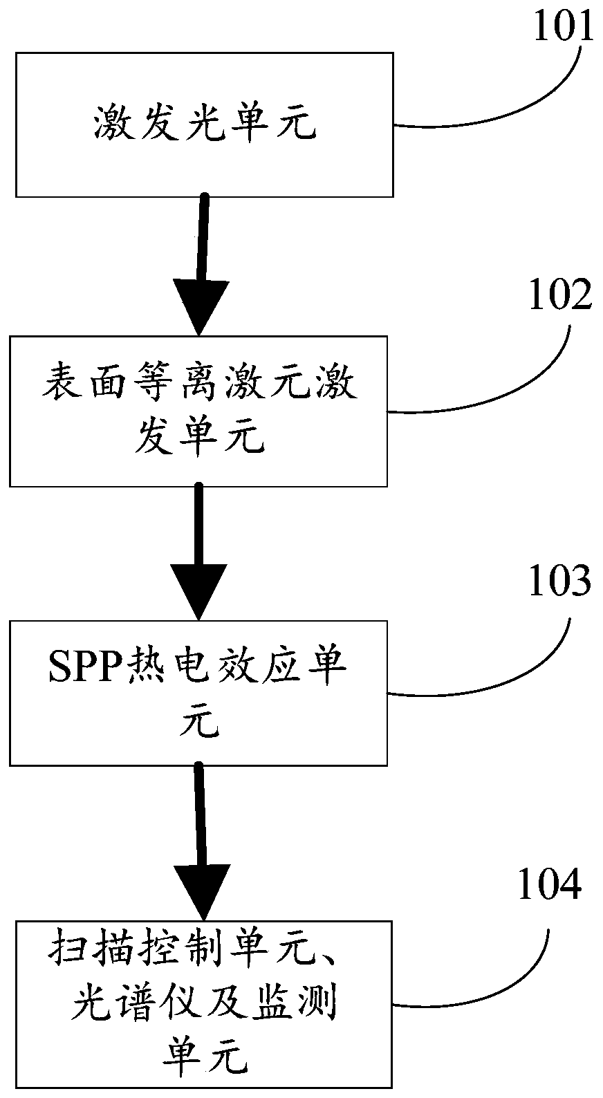
[0042] Specifically, the excitation light unit 101 is used to generate a radially polarized light beam, and make the radially polarized light beam incident to the surface plasmon excitation unit 102 . The polarized light beam generated by the excitation light unit is to react with the plasmon excitation unit to achieve the planned purpose.

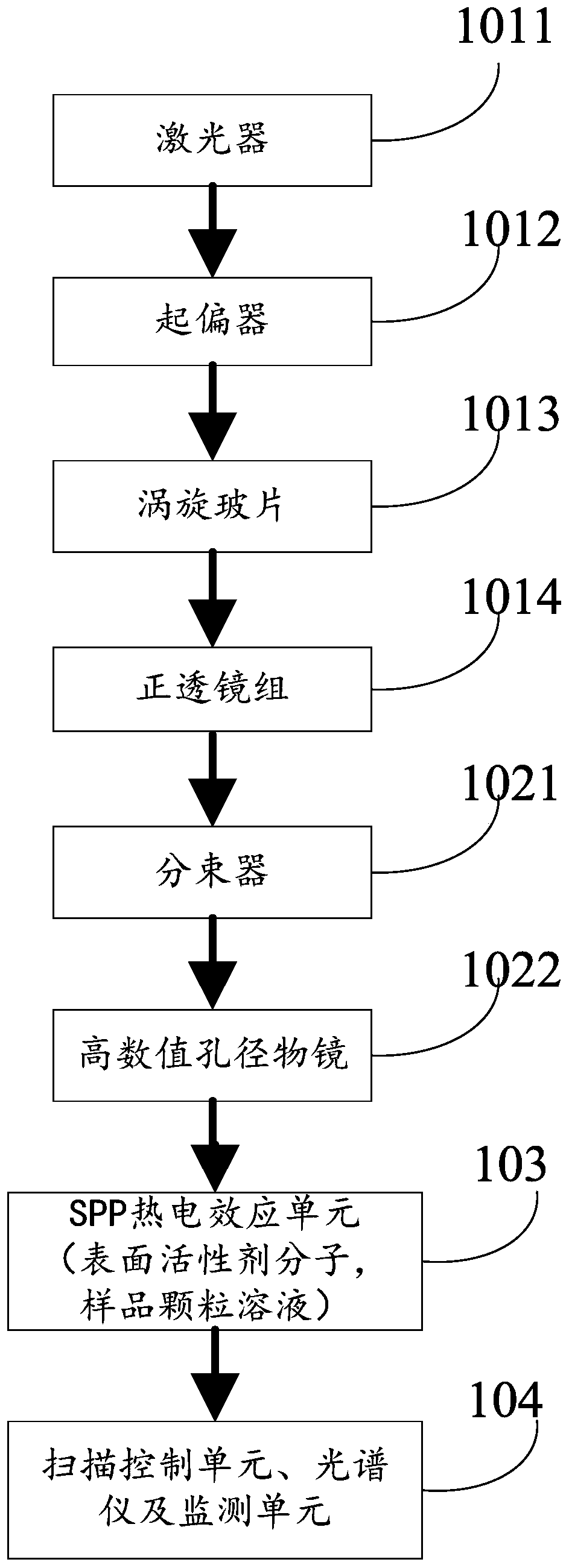
[0043] Specifically, the excitation light unit 101 includes: a laser 1011, a polarizer 1012, a vortex wave plate 1013, and a positive lens group 1014;

[0044] The laser 1011 is used to generate a laser beam with a preset wavelength, and inject the laser beam into the polarizer 1012;

[0045] The polarizer 1012 is used to make the incident laser beam into a linearly polarized light, and the obtained linearly polarized light is incident on the vortex wave plate 1013;

[0046] The vortex wave plate 1013 is used to change the incident linearly polarized light into radially polarized light, and the obtained radially polarized light is inciden...


PUM


Abstract

The invention provides a Raman spectrum scanning imaging system based on SPP thermoelectric optical tweezers. The system includes an excitation light unit, a surface plasmon excitation unit, and an SPP thermoelectric effect unit. Light beams generated by the excitation light unit are emitted to the surface plasmon excitation unit, the surface plasmon excitation unit excites a converging surface plasmon special light field under light beam irradiation, and the SPP thermoelectric effect unit carries out optical tweezers capture in the special light field. Stable capture on nano-level particles can be realized, and dynamic Raman spectrum scanning imaging in a range of a to-be-measured sample can be realized under SPP field enhancement.

Description

technical field [0001] The invention relates to the technical field of near-field optics, in particular to a Raman spectrum scanning imaging system based on SPP thermoelectric optical tweezers. Background technique [0002] In the field of optical manipulation, because metal particles have stronger reflection and absorption characteristics than ordinary dielectric materials, it usually makes manipulation more difficult. On the one hand, for nanometer-sized structures, usually the smaller the size, the higher the laser power required for manipulation, and metal nanomaterials will have a strong thermal effect under laser irradiation, which further increases the difficulty of optical manipulation; on the other hand, For metal particles with a micron size (on the order of hundreds of nanometers to several microns), the focused spot in traditional laser optical tweezers will generate a huge scattering force, which will cause the metal particles to be pushed away and cannot be sta...

Claims


Application Information

Patent Timeline
IPC IPC(8): G02B5/00G02B27/28G21K1/00
CPCG02B5/008G02B27/286G21K1/006
Inventor 张聿全余家豪汪先友付孔文闵长俊袁小聪
Owner SHENZHEN UNIV
Learn More