Complete-upper-air-intake combustor with centrally-arranged mixing cavity

A burner and mixing chamber technology, applied in burners, gas fuel burners, combustion methods, etc., can solve problems such as poor gas adaptability, airflow interference, and lack of promotion.

Pending Publication Date: 2020-01-07
陈毅
View PDF0 Cites 0 Cited by
  • Summary
  • Abstract
  • Description
  • Claims
  • Application Information

AI Technical Summary

Problems solved by technology

[0003] Some of the existing upward air-intake burners generally have small ejectors, which cannot meet the large-load ejection requirements, so the heat load is generally small, only about 3.5-4.0kW, and the combustion flame is small, which cannot reach Chinese food. stir fry demand
At the same time, because the injector is small, the adaptability to gas is poor, and the combustion stability is poor, so it has not been well promoted.
[0004] There is airflow interference between the primary air and the secondary air when some existing complete upward air intake burners are working, frequent air grabbing occurs, and poor combustion stability

Method used


Image

  • Complete-upper-air-intake combustor with centrally-arranged mixing cavity
  • Complete-upper-air-intake combustor with centrally-arranged mixing cavity
  • Complete-upper-air-intake combustor with centrally-arranged mixing cavity

Examples


Embodiment 1

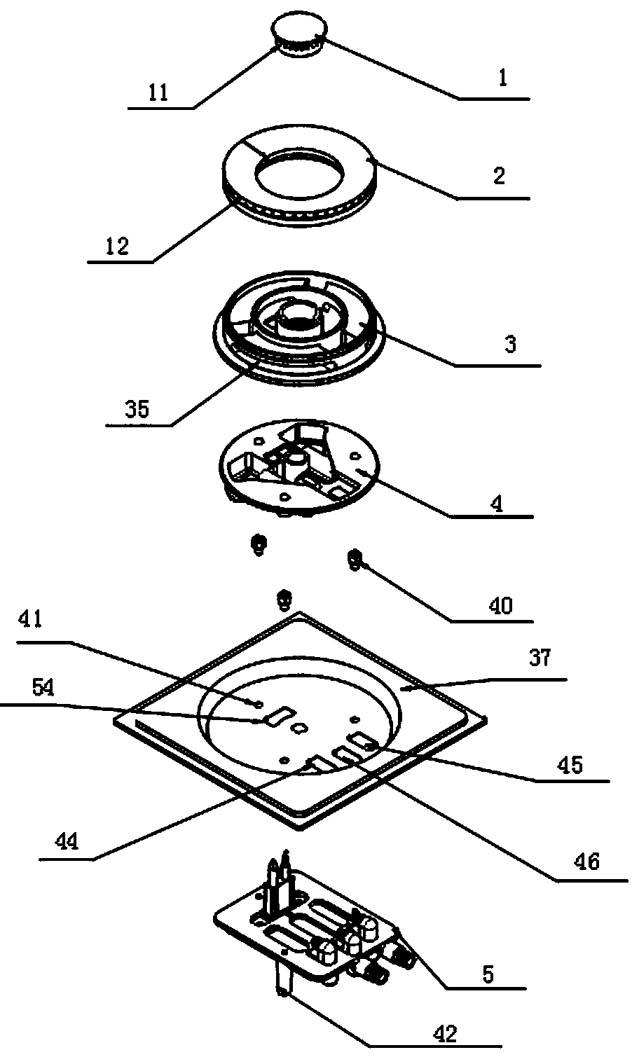
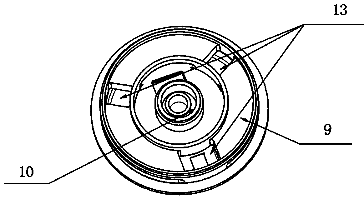
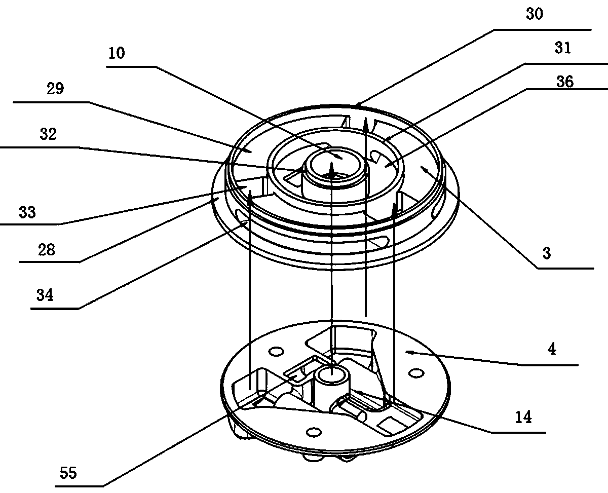
[0065] refer to Figure 1-Figure 13 , the complete upper air intake burner in the middle of the mixing chamber, including the central fire cover 1, the outer ring fire cover 2, the burner head 3, the burner bottom 4, the burner support 5, the central fire injector 6, the first The main fire ejector 7, the second main fire ejector 8, the burner head 3 is provided with an outer ring fire distribution chamber 9 and a central fire mixing chamber 10, and the central fire cover 1 is provided with a central fire outlet hole 11 , the central fire cover 1 covers the central fire mixing chamber 10, the outer ring fire cover 2 is provided with an outer ring fire outlet hole 12, the outer ring fire cover 2 is covered on the outer ring fire distribution chamber 9, and the burner head 3 There is also a gas distribution channel 13 inside, the upper end of the gas distribution channel 13 communicates with the fire distribution chamber 9 of the outer ring fire, the bottom 4 of the burner is pr...

Embodiment 2

[0097] The difference between this embodiment and embodiment 1 is:

[0098] refer to Figure 14-Figure 16 , the complete upward air intake burner also includes an anti-dry heating probe 65, the head of the anti-dry heating probe 65 passes through the burner support 5, the flange 38 at the bottom of the burner 4, and the middle partition of the burner head 3 Stretch out the central fire cover 1 upper surface after 28. At this time, the burner support 5, the flange 38 of the burner bottom 4, the middle partition 28 of the burner head 3, and the central fire cover 1 are all provided with anti-dry probe penetration holes (not shown in the figure). out).

[0099] The inlet port 61 of the central fire ejector 6 is positioned at one side of the lower surface of the burner bottom 4, and the inlet port 71 of the first main fire ejector 7 and the inlet port 81 of the second main fire ejector 8 are all located at the combustion chamber. The other side of the lower surface of the devic...


PUM


Abstract

The invention discloses a complete-upper-air-intake combustor with a centrally-arranged mixing cavity. The combustor comprises a center burner cap, an outer ring burner cap, a combustor head, a combustor bottom, a combustor support, a center fire ejector, a first main fire ejector, and a second main fire ejector. An outer ring fire dividing cavity and a center fire mixing cavity are formed in thecombustor head, an air dividing channel is formed in the combustor head, the upper end of the air dividing channel communicates with the outer ring fire dividing cavity, the main fire centrally-arranged mixing cavity is formed in the combustor bottom, and the lower end of the air dividing channel communicates with the main fire centrally-arranged mixing cavity. The combustor is compact in structure, good in ejection capacity, high in stability, large in combustion power and high in work reliability.

Description

technical field [0001] The invention relates to a complete upward air-intake burner placed in the middle of a mixing chamber. Background technique [0002] At present, in the gas cooker and integrated stove industry, most of the burners use the bottom-inlet combustion technology. Although some are upward-inlet, they are based on the bottom-inlet burner, and the burner head is lifted. In order to realize the supply of secondary air from the top of the panel, but the supplement of primary air does not realize the upward air intake, so it cannot be called a complete upward air intake technology. And when the burner is applied to an ordinary gas stove, the cabinet door needs to be provided with ventilation holes; Both the size and the stability of the pull wire operating mechanism directly affect the working reliability of the burner. [0003] Some of the existing upward air-intake burners generally have small ejectors, which cannot meet the large-load ejection requirements, s...

Claims


Application Information

Patent Timeline
IPC IPC(8): F23D14/04F23D14/58F23D14/64F24C3/10
CPCF23D14/04F23D14/58F23D14/64F24C3/10
Inventor 陈毅周国来
Owner 陈毅
Why Eureka
Try Eureka