Self-positioning high-precision aperture measuring device
A measuring device and self-positioning technology, which is applied in the direction of measuring devices, optical devices, instruments, etc., can solve the problems of poor precision, complex structure, low efficiency, etc., and achieve the effect of fast measurement and correctness
- Summary
- Abstract
- Description
- Claims
- Application Information
AI Technical Summary
Problems solved by technology
Method used
Image

Examples
Embodiment 1
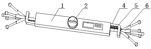
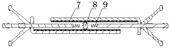
[0026] A self-positioning high-precision aperture measurement device includes a bracket 1, a coarse adjustment knob 2, an adjustable support arm 4, a measuring rod 5, and a self-positioning structure 6. There are two adjustable support arms 4 and two measuring rods 5, and there are two Both ends of 1 are respectively provided with an adjustable support arm 4 and a measuring rod 5, each adjustable support arm 4 is provided with a self-positioning structure 6, and a thick knob is provided on the shell of the support 1. The bracket 1 is provided with a chute; the coarse adjustment knob 2 is located in the center of the bracket 1, and below the coarse adjustment knob 2 is a high-precision straight / helical gear 8, which can be unlocked and locked by pulling it up and pressing it down.
[0027] An electronic module can also be installed on the shell of the bracket 1, which can realize μ-level high-precision distance measurement, and can display the measured value and power percentage...
Embodiment 2
[0030] Such as figure 1 As shown, a self-positioning high-precision aperture measuring device includes a bracket 1, a coarse adjustment knob 2, an adjustable support arm 4, a measuring rod 5, and a self-positioning structure 6. The device utilizes damping rods in the horizontal and vertical directions and The coordinated movement of the universal ball reaches the state of force balance, ensuring that the measured length direction is located in the diameter direction of the radial tangent circle. The linear grating scale is used to achieve fast and accurate measurement of the aperture. This device needs to be used in conjunction with an outer micrometer.
[0031] Coarse adjustment knob 2 includes: coarse adjustment knob 2, high-precision straight / helical gear 8;
[0032] The adjustable support arm 4 includes: the adjustable support arm 4, the straight / helical rack 7 of the support arm;
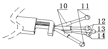
[0033] The self-positioning structure 6 includes: a horizontal damping rod 10, a horizonta...
PUM
 Abstract
Description
Claims
Application Information
PatSnap Eureka turns technology decisions into work you can execute. Powered by our Innovation Knowledge Graph, it runs expert workflows across engineering, life sciences, materials and intellectual property. Get your review-ready output in minutes.


