
Preparation method for nano CT sample of catalytic layer of proton exchange membrane fuel cell

A technology of proton exchange membranes and fuel cells, which is applied in the preparation of test samples, material analysis using wave/particle radiation, and material analysis. To achieve the effect of reducing the difficulty of sample preparation operation, strengthening the value of engineering application, and reducing processing time

Inactive Publication Date: 2020-01-07
WUHAN UNIV OF TECH
View PDF4 Cites 0 Cited by
  • Summary
  • Abstract
  • Description
  • Claims
  • Application Information

AI Technical Summary

Problems solved by technology

However, in terms of sample preparation, the commonly used embedding section method and the FIB Lift-Out method cannot simultaneously ensure high imaging quality, easy operation, and low cost requirements.
The embedding section method can only prepare two-dimensional thin-sheet samples, and cannot meet the requirements of the field of view in three-dimensional space. It can only be imaged by a non-full-angle sector scan method, which will easily lead to the loss of three-dimensional structure information of the sample and reduce the imaging quality. Samples for 3D imaging
At the same time, it is easy to damage the catalytic layer or membrane structure when slicing
Although the FIBLift-Out method can be used for three-dimensional sample preparation, the catalytic layer of the fuel cell not only has a complex nanopore structure, but also has a soft material, is sensitive to temperature, and is tightly adhered to the proton exchange membrane. The Out method takes a long time to prepare samples, is complicated to operate, has a low success rate, and is not suitable for large-scale sample preparation.

Method used


Image

  • Preparation method for nano CT sample of catalytic layer of proton exchange membrane fuel cell
  • Preparation method for nano CT sample of catalytic layer of proton exchange membrane fuel cell
  • Preparation method for nano CT sample of catalytic layer of proton exchange membrane fuel cell

Examples


Embodiment Construction

[0030] For a better understanding of the present invention, the following examples are further descriptions of the present invention, but the content of the present invention is not limited to the following examples.

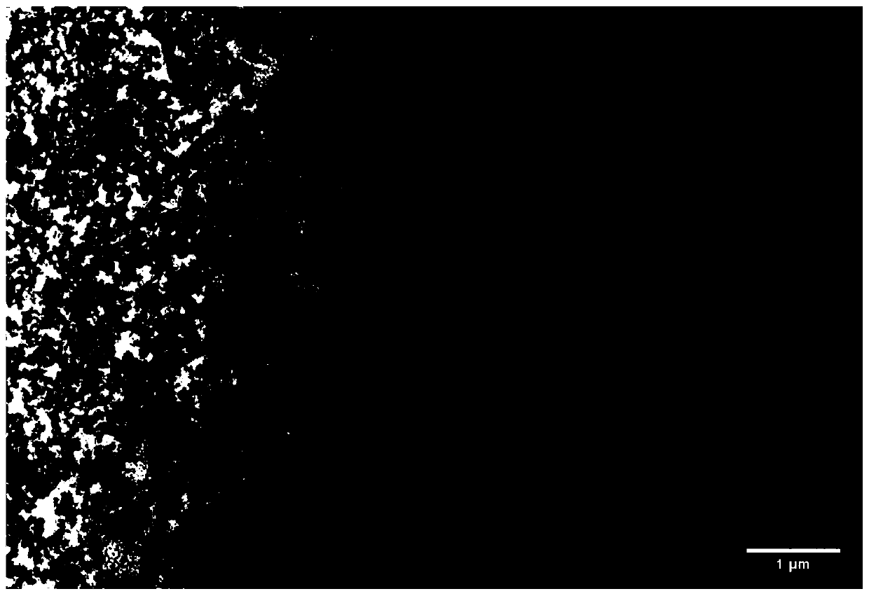
[0031] In this embodiment, the nano-CT sample of the commercial standard proton exchange membrane fuel cell catalyst layer derived from Wuhan University of Technology New Energy Company was successfully prepared by using the method of the present invention. figure 1 It is the TEM figure of the proton exchange membrane cathode catalytic layer of the present invention, as can be seen from the figure, the catalytic layer has a complex pore structure, and the pore size distribution is approximately between 10-1um; it is prepared by the following steps:

[0032] First, a large piece of CCM sample is cut with a scalpel into a CCM sample strip 1 with a sharp tip, and then screened under an optical microscope to keep a CCM sample strip 1 with a tip width of less than 60 ...


PUM

PropertyMeasurementUnit
widthaaaaaaaaaa
thicknessaaaaaaaaaa
lengthaaaaaaaaaa

Abstract

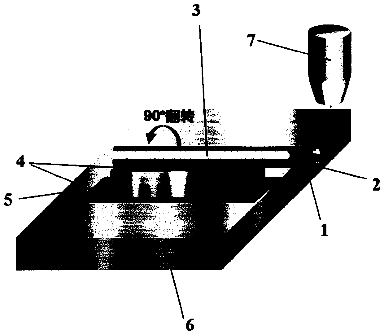
The invention belongs to the field of fuel cells, and particularly relates to a preparation method for a nano CT sample of a catalytic layer of a proton exchange membrane fuel cell. The preparation method comprises the following steps of (1) prefabricating a film-coated sample of the catalytic layer of the proton exchange membrane fuel cell into a sample strip with a tip; (2) adhering the sample strip to an objective table and projecting the tip of the sample strip from the objective table; and (3) fixing the objective table adhered with the sample strip to an FIB (Focused Ion Beam) workbench,processing the tip of the sample strip for the first time through an FIB, cutting off a redundant sample area by the FIB, then turning over the objective table adhered with the sample strip by 90 degrees, and processing the tip of the sample strip for the second time to prepare the nano CT sample of the catalytic layer of the proton exchange membrane fuel cell. According to the method, the FIB isused for fine processing, so that the integrity of the structure of the sample of the catalytic layer of the proton exchange membrane fuel cell, particularly the three-dimensional porous structure inthe catalytic layer can be effectively ensured.

Description

technical field [0001] The invention belongs to the field of fuel cells, and in particular relates to a method for preparing a nano-CT sample of a catalytic layer of a proton exchange membrane fuel cell. Background technique [0002] The catalytic layer of proton exchange membrane fuel cell is mainly composed of Nafion wrapped Pt / C catalyst particle aggregates, and then forms a complex heterogeneous multiphase structure including pores, Nafion phase and Pt / C phase. The mesopore structure of the catalytic layer is responsible for the transport of reactive gases and generated water. Nafion is mainly responsible for proton conduction, Pt is the catalytic center, and C is responsible for electron transport. The three-phase interface in the structure directly determines the performance and efficiency of the battery. Therefore, it is very important to explore the internal relationship between the three-dimensional structure of the catalytic layer of the proton exchange membrane fu...

Claims


Application Information

Patent Timeline
Patent Type & Authority Applications(China)
IPC IPC(8): G01N23/046G01N1/36
CPCG01N1/36G01N23/046
Inventor 邓兆汪如意官树猛李赏潘牧
Owner WUHAN UNIV OF TECH
Learn More