Electronic pipette

A pipette and electric technology, applied in instruments, analytical materials, etc., can solve the problems of large harmful overturning moment, large vertical distance, fatigue deformation, etc., and achieve the shortest vertical distance, low price, and reduce fatigue deformation. Effect

Pending Publication Date: 2020-01-07
PREMEDICAL LAB
View PDF0 Cites 2 Cited by
  • Summary
  • Abstract
  • Description
  • Claims
  • Application Information

AI Technical Summary

Problems solved by technology

[0005] The purpose of the present invention is to provide an electric pipette, which can not only solve the problem of high price in the prior art using small-diameter high-speed motors, but also solve the reciprocating axis of the pipetting actuator in the prior art usi

Method used


Image

  • Electronic pipette
  • Electronic pipette
  • Electronic pipette

Examples


Embodiment Construction

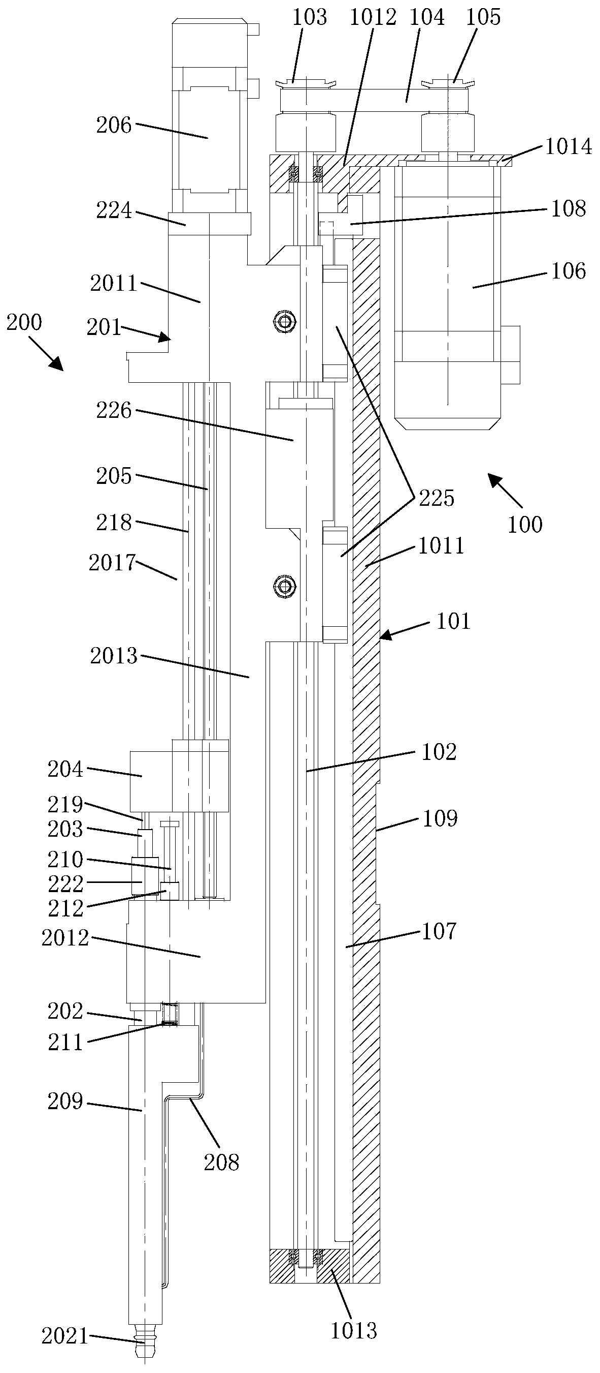
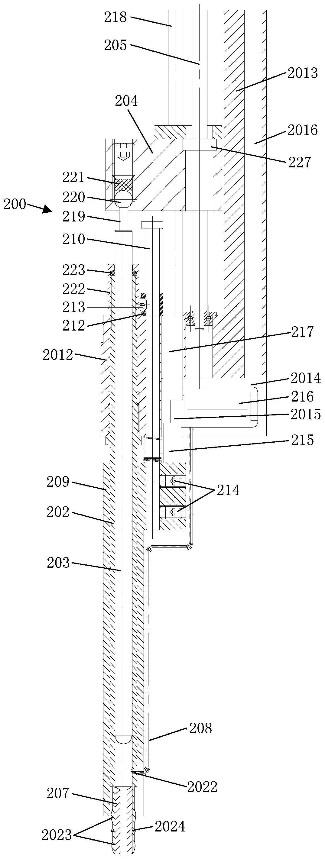
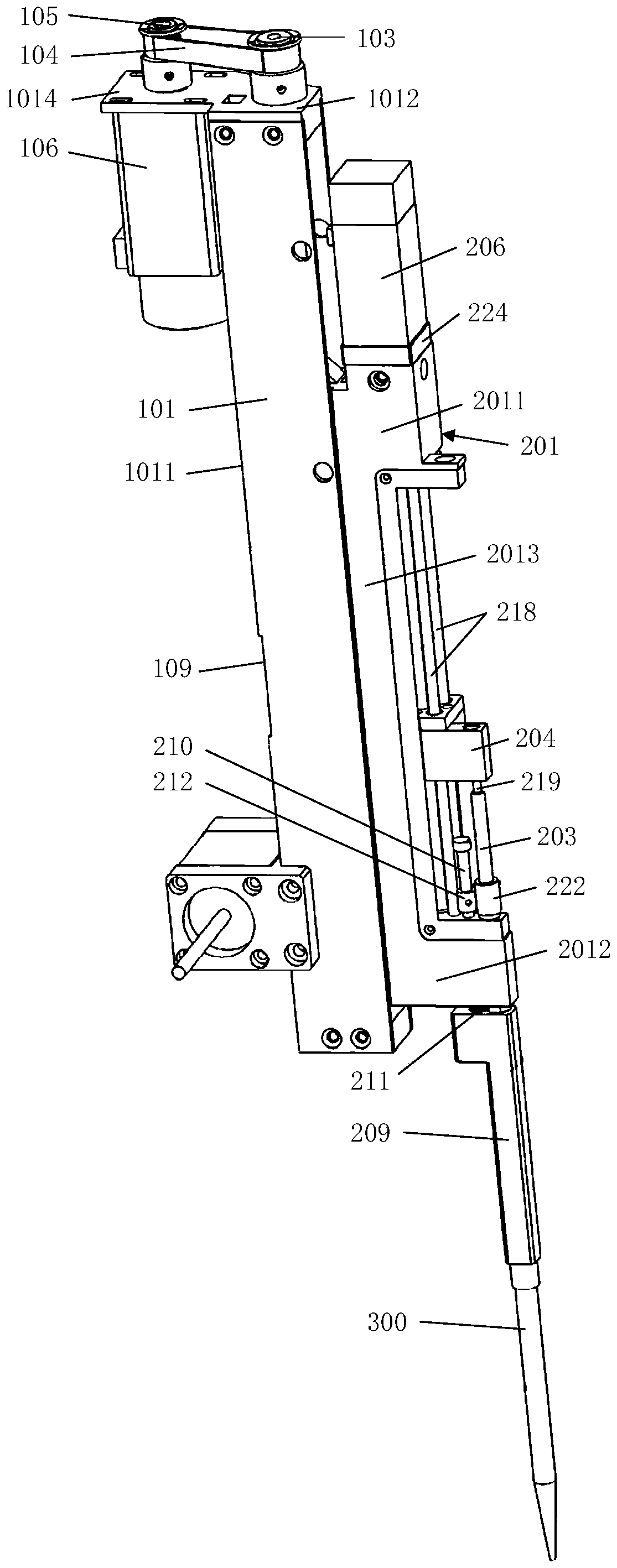
[0044] In order to have a clearer understanding of the technical features, purposes and effects of the present invention, the specific implementation manners of the present invention will now be described with reference to the accompanying drawings. In describing the present invention, it is to be understood that the terms "upper", "lower", "front", "rear", "left", "right", "vertical", "horizontal", "top", The orientation or positional relationship indicated by "bottom", "inner", "outer", etc. is based on the orientation or positional relationship shown in the drawings, and is only for the convenience of describing the present invention and simplifying the description, rather than indicating or implying the referred device Or elements must have a certain orientation, be constructed and operate in a certain orientation, and thus should not be construed as limiting the invention. In addition, the terms "first", "second", etc. are used for descriptive purposes only, and should no...


PUM


Abstract

The invention provides an electronic pipette, comprising a loading mechanism and an execution mechanism, wherein the loading mechanism comprises a support frame provided with a fixed pivot, a first screw, a driven belt pulley and a driving belt pulley connected with the driven belt pulley by virtue of a synchronous belt as well as a first motor; the execution mechanism is located at the front sideof the fixed pivot and comprises a rack, an injection pipe, a plunger vertically inserted into and arranged in the injection pipe, a dislocation sliding block connected with the plunger and a secondscrew connected with the dislocation sliding block by virtue of a screw thread as well as a second motor, the first screw rotates a driving rack to drive the injection pipe to axially move, the injection pipe axially moves downward to be inserted into and connected with a pipetting head, the second screw rotates and drives the dislocation sliding block to drive the plunger to axially move, and theplunger axially moves to inhale a liquid into the pipetting head or discharge the liquid out the pipetting head. The electronic pipette provided by the invention adopts the conventional motor, can realize minimization of a distance between a reciprocating motion axis of the pipetting execution mechanism and a vertical line of a pivot of the mechanism and alleviates harmful overturning moment andfatigue deformation which are produced when the pipetting execution mechanism moves downward along the axis to be frequently in press-in type connection with the pipetting head.

Description

technical field [0001] The invention relates to a sample adding device, in particular to an electric pipette. Background technique [0002] In the detection work in the fields of medicine, food, biology, etc., it is necessary to carry out a lot of pre-processing work on biological materials and samples (usually in liquid state). Using high-throughput automated biological sample pre-processing equipment, it can be completed in batches in a short time For operations such as pipetting, adding samples, and mixing, the electric pipette is the core technical unit in the automatic processing system of biological samples. According to the different suction driving methods of electric pipettes for liquids, electric pipettes are divided into two types: gas-liquid mixing displacement type and gas displacement type. [0003] The gas-liquid mixing displacement pipette adopts the liquid plunger, and the liquid plunger and the sample liquid are separated by the air gap retained in the pip...

Claims


Application Information

Patent Timeline
IPC IPC(8): G01N35/10
CPCG01N35/1009
Inventor 范光伟
Owner PREMEDICAL LAB
Why Eureka
Try Eureka