Current transformer capable of broadband wide-width measurement and magnetic interference resistance

A current transformer and magnetic interference technology, applied in the field of transformers, can solve the problems of complex secondary coil winding process, large size, large temperature error of winding copper wire, etc., and achieve strong resistance to external magnetic field interference, strong resistance to Effect of external electromagnetic interference and small measurement error

Pending Publication Date: 2020-01-07
HEBEI SHENKE ELECTRONICS CO LTD
View PDF0 Cites 7 Cited by
  • Summary
  • Abstract
  • Description
  • Claims
  • Application Information

AI Technical Summary

Problems solved by technology

[0002] my country refers to the standard structure of IEC / TC13 and the international proposal of OIML R46 electric energy meter to formulate the corresponding electric energy measurement and load control standard system. Higher requirements are put forward for current transformers for electric energy meters: wide dynamic range, high reliability, high sensitivity, high temperature stability, etc., while traditional electromagnetic current transformers have complex secondary coil winding process and winding Copper wire has disadvantages such as large temperature error, large size, non-linearity, easy saturation, small dynamic range, and susceptibility to external magnetic field interference, which can no longer meet the needs of industry development.
Especially in the new standard system, when the power factor is equal to 0.5L, the DC and even harmonics of the electric energy meter - the half-wave rectification waveform test stipulates the requirements, and the traditional electromagnetic current transformer can no longer meet the standard requirements.

Method used


Image

  • Current transformer capable of broadband wide-width measurement and magnetic interference resistance
  • Current transformer capable of broadband wide-width measurement and magnetic interference resistance
  • Current transformer capable of broadband wide-width measurement and magnetic interference resistance

Examples


Embodiment Construction

[0024] Below in conjunction with accompanying drawing and specific embodiment the present invention is described in detail:

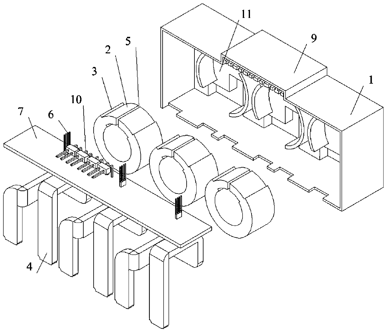
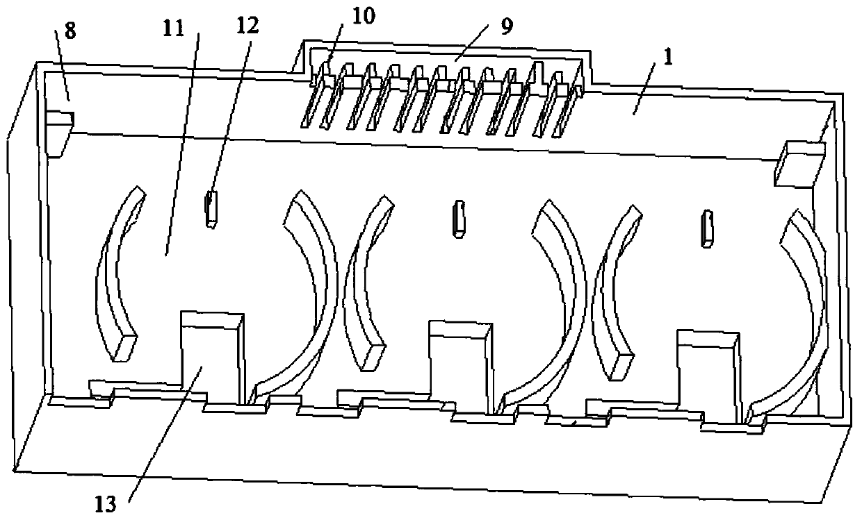
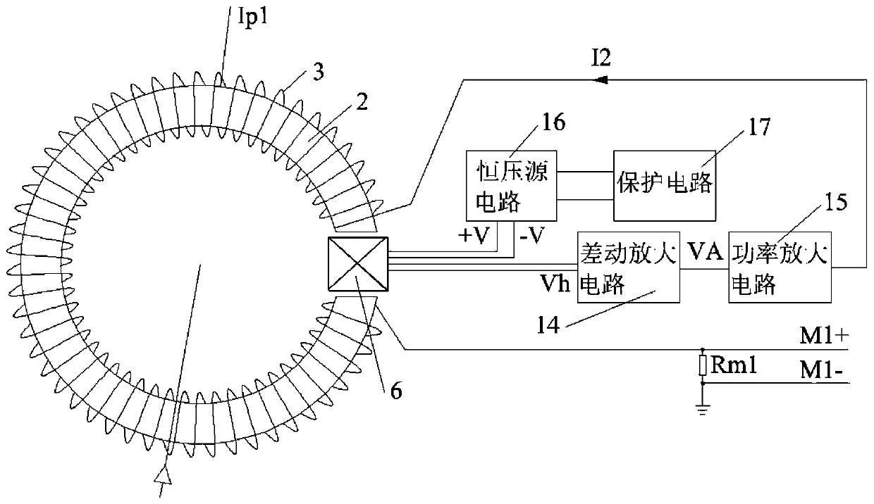
[0025] Specific examples, such as Figure 1 to Figure 8 As shown, a current transformer with broadband, wide-width measurement and anti-magnetic interference capability includes a casing 1, a magnetic core 2 arranged in the casing 1, a secondary coil 3 wound on the magnetic core 2, and one end located at The outside of the housing 1 and the other end passes through the inner ring side of the magnetic core 2 and extends to the primary current connection piece 4 outside the housing 1. The current transformer also includes a signal conditioning circuit arranged in the housing 1. The signal conditioning circuit includes sequential connections. The induction circuit, the differential amplifier circuit 14, the power amplifier circuit 15, the Hall chip 6 of the induction circuit is fixed in the air gap 5 opened on the magnetic core 2, and the output terminal o...


PUM


Abstract

The invention discloses a current transformer capable of broadband wide-width measurement and magnetic interference resistance, and belongs to the technical field of transformers. A signal conditioning circuit comprises an induction circuit, a differential amplification circuit and a power amplification circuit; a Hall chip of the induction circuit is fixed in an air gap formed in the magnetic core; the output end of the power amplification circuit is connected with one end of a secondary coil; the other end of the secondary coil is connected in series with a first sampling resistor Rm1 and then is grounded; the point where the first sampling resistor Rm1 is grounded serves as a negative signal output end M1-; the point where the first sampling resistor Rm1 is connected with the secondarycoil serves as a positive signal output end M1+; the signal conditioning circuit further comprises a constant voltage source circuit; and the output end of the constant voltage source circuit is connected with the Hall chip. Under the condition that there is external magnetic interference in a broadband and wide-width range, the current can be still measured in high precision, DC and harmonic components in the current can be accurately measured, and measurement is not influenced by a power factor.

Description

technical field [0001] The invention belongs to the technical field of transformers, and relates to a current transformer, in particular to a current transformer with wide-band, wide-width measurement and anti-magnetic interference capabilities. Background technique [0002] my country refers to the standard structure of IEC / TC13 and the international proposal of OIML R46 electric energy meter to formulate the corresponding electric energy measurement and load control standard system. Higher requirements are put forward for current transformers for electric energy meters: wide dynamic range, high reliability, high sensitivity, high temperature stability, etc., while traditional electromagnetic current transformers have complex secondary coil winding process and winding Copper wire has disadvantages such as large temperature error, large size, non-linearity, easy saturation, small dynamic range, and susceptibility to external magnetic field interference, which can no longer mee...

Claims


Application Information

Patent Timeline
Patent Type & Authority Applications(China)
IPC IPC(8): G01R15/18G01R15/20G01R1/18G01R19/00
CPCG01R1/18G01R15/185G01R15/202G01R19/0092
Inventor 刘继志谢志远王力崇王茹陈帅芝戎松白晓亮
Owner HEBEI SHENKE ELECTRONICS CO LTD
Why Eureka
Try Eureka