Linear generator
A linear generator and coil technology, applied to electrical components, electromechanical devices, etc., can solve problems such as low efficiency and complex structure, and achieve the effect of low cost, obvious advantages, and simple structure
- Summary
- Abstract
- Description
- Claims
- Application Information
AI Technical Summary
Problems solved by technology
Method used
Image

Examples
Embodiment 1
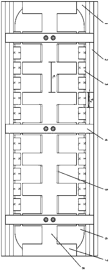
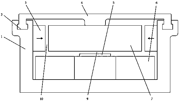
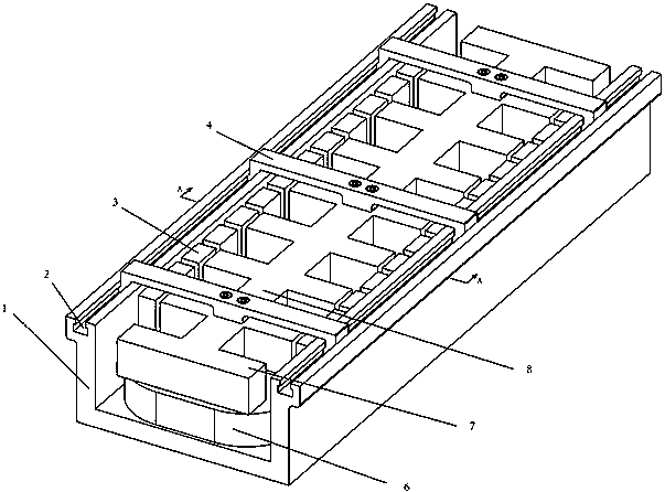
[0034] A linear generator such as Figure 1-9 As shown, it includes the primary and the secondary; the primary includes the primary yoke 1, the permanent magnet array and the coil 6, the primary yoke is a U-shaped rectangular parallelepiped structure, the center of the bottom is provided with a primary raised part 5, and the coil is wound on the raised part On the top, a ring-shaped large coil is formed, and two permanent magnet arrays 3 are arranged on both sides of the U shape. The permanent magnets in the permanent magnet array on each side are arranged alternately and evenly with N and S poles, that is, the pole pitch between the permanent magnets They are all the same, the polarity of the permanent magnets at the corresponding positions on both sides is the same, the permanent magnets on both sides are arranged symmetrically, and the magnetization direction of the permanent magnets is the horizontal direction; Made of magnetically permeable material, the secondary include...
Embodiment 2
[0037] A linear generator such as Figure 10 As shown, the difference from the first embodiment is that the secondary teeth 7 at the corresponding positions at both ends of the secondary are staggered by half the pole pitch (the pole pitch is at figure 1 It has been marked in , which is the width of the permanent magnet plus the distance between adjacent permanent magnets, and the pitch of the secondary teeth is the width of the secondary teeth plus the distance between adjacent secondary teeth), from figure 1 It can be seen in the figure that the two first secondary teeth on the left and right sides of the front end of the secondary yoke 8 are staggered by half the pole pitch in the length direction of the secondary yoke. This setting can minimize the reluctance fluctuation force. Magnetic resistance is the electromagnetic force that exists between the permanent magnet and the mover core when the winding is not energized or disconnected. In the direction of motion, this magne...
Embodiment 3
[0040] A linear generator such as Figure 12 As shown, the difference from the first embodiment is that the two coils are respectively wound on both sides of the primary raised portion 5 at the bottom of the primary yoke 1 , or on the two sides of the primary yoke, and the others are the same as the first embodiment.
[0041] During the reciprocating movement of the secondary under the action of external power, when the secondary teeth 7 are aligned with the poles of the permanent magnet, the magnetic circuit passes through the secondary teeth, the secondary yoke 8, the first air gap 9, the primary raised part, Primary yoke, permanent magnet, and second air gap 10; when the secondary teeth straddle the two primary permanent magnets, the magnetic circuit is in the longitudinal direction, and the secondary teeth form a closed loop with the magnetic field of the adjacent two permanent magnets; when again, When the secondary teeth are aligned with the poles of the permanent magnet...
PUM
 Abstract
Description
Claims
Application Information
 - R&D
- Intellectual Property
- Life Sciences
- Materials
- Tech Scout
- Unparalleled Data Quality
- Higher Quality Content
- 60% Fewer Hallucinations
Browse by: Latest US Patents, China's latest patents, Technical Efficacy Thesaurus, Application Domain, Technology Topic, Popular Technical Reports.
© 2025 PatSnap. All rights reserved.Legal|Privacy policy|Modern Slavery Act Transparency Statement|Sitemap|About US| Contact US: help@patsnap.com