
Movement transmission device for vehicle wiper device

A transmission device and vehicle technology, applied in vehicle cleaning, transportation and packaging, vehicle maintenance, etc., to achieve the effects of improving comfort, reducing wear, reducing noise and vibration

Pending Publication Date: 2020-01-07
VALEO AUTOSYSTY
View PDF12 Cites 0 Cited by
  • Summary
  • Abstract
  • Description
  • Claims
  • Application Information

AI Technical Summary

Problems solved by technology

However, the above problems usually exist on the passenger side

Method used


Image

  • Movement transmission device for vehicle wiper device
  • Movement transmission device for vehicle wiper device
  • Movement transmission device for vehicle wiper device

Examples


Embodiment Construction

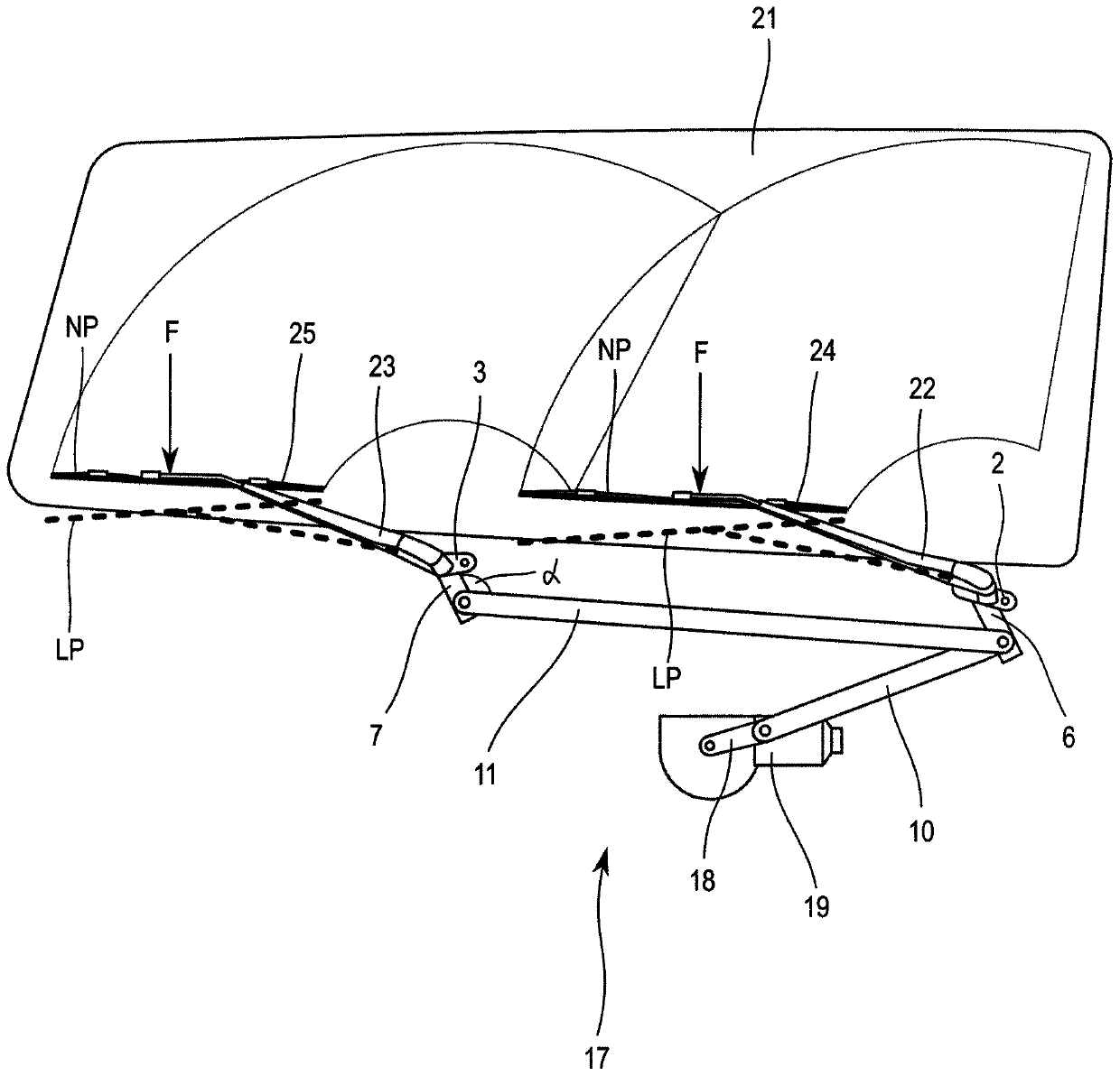
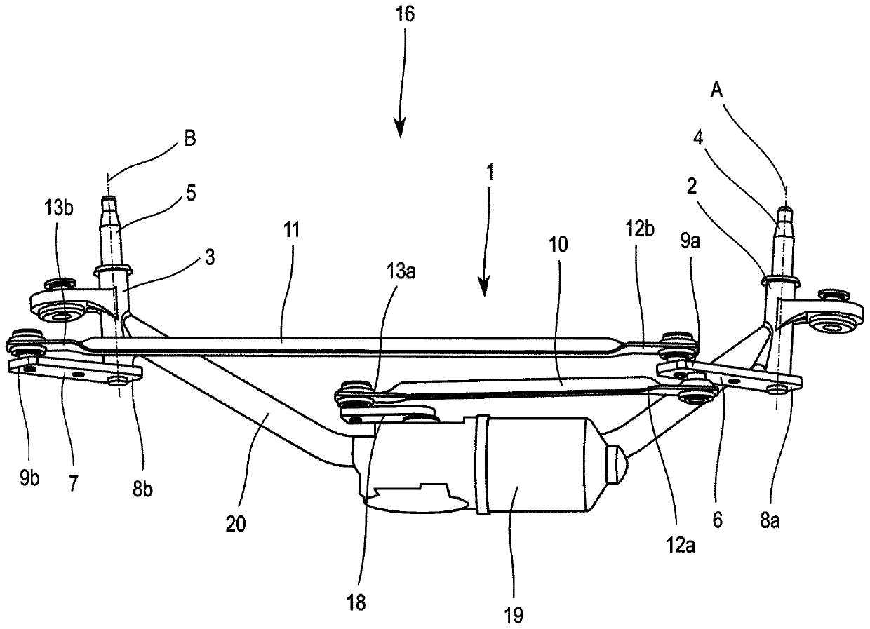
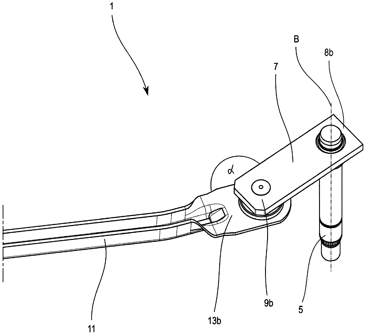
[0043] figure 1 A vehicle wiper device 17 for wiping a windscreen 21 of a vehicle is shown. The vehicle wiper arrangement 17 comprises a wiper module 16, figure 2 The wiper module is shown in detail in . The wiper module 16 includes a transmission 1 which transmits drive from a wiper motor 19 to a first wiper arm 22 and a second wiper arm 23 , thereby providing the wiper arms 22 , 23 reciprocating motion. A first wiper blade 24 and a second wiper blade 25 are attached to a first wiper arm 22 and a second wiper arm 23, respectively, for wiping a windshield 21 of a vehicle. wipe. The wiper blades 24 , 25 are placed in close proximity to the windshield 21 so that the wiper blades 24 , 25 can wipe the windshield 21 of the vehicle.

[0044] as from figure 1 As can be seen, the wiper arms 22 , 23 can be lowered into the lowered position LP (dashed line), for example due to an acting external force F applied to the wiper blades 24 , 25 or the wiper arms 22 , 23 . The lowered ...


PUM


Abstract

The present invention relates to a movement transmission device (1') for a vehicle wiper device (17) comprising a pivot shaft housing (3') receiving a pivot shaft (5), a crank (7') having a first end(8b') and a second end (9b'). The first end of the crank is fixed to the pivot shaft and the second end of the crank is able to be linked to a link rod (11) transmitting a movement to the crank. The pivot shaft housing comprises limiting means (14) for limiting the movement of the crank.

Description

technical field [0001] The invention relates to a transmission for a vehicle wiper device. Background technique [0002] Transmissions for vehicle wiper assemblies are generally known. Wiper devices are used for wiping the windshields of vehicles, in particular the windshields of passenger cars. The transmission transmits drive from the motor of the vehicle wiper assembly to the wiper arms to wipe the windshield of the vehicle. A rubber wiper blade is attached to the wiper arm for wiping over the surface of the windshield to be wiped. However, the present invention is not limited to use on cars, but is also used in trucks, trains, and other vehicles where significant forces affect the wiper arms (from the high height of the vehicle). velocity or the force of mass air movement). [0003] The transmission provides reciprocating motion of the wiper arms and wiper blades attached thereto to wipe the windshield of the vehicle. Reciprocation means that the wiper arm with the ...

Claims


Application Information

Patent Timeline
Patent Type & Authority Applications(China)
IPC IPC(8): B60S1/24B60S1/34B60S1/18
CPCB60S1/185B60S1/24B60S1/3495
Inventor 卢卡斯·亨泽尔罗曼·玛查科
Owner VALEO AUTOSYSTY
Learn More