Melting device for curing agent coating producion

A melting device and curing agent technology, applied in the direction of melting, chemical instruments and methods, chemical/physical processes, etc., can solve the problems that cannot meet the production needs of the factory, easily adhere to the inside of the melting device, and inconvenient cleaning work, etc., to avoid The effect of causing harm to the body, good filtering effect, and convenient unloading work

Inactive Publication Date: 2020-01-10
湖北汉耐尔新材料科技有限公司
View PDF0 Cites 4 Cited by
  • Summary
  • Abstract
  • Description
  • Claims
  • Application Information

AI Technical Summary

Problems solved by technology

The general melting device tends to stick to the inside of the melting device after melting the material, which not only brings great inconvenience to people's cleaning work, but also causes waste of resources and cannot meet the production needs of the factory.

Method used


Image

  • Melting device for curing agent coating producion
  • Melting device for curing agent coating producion
  • Melting device for curing agent coating producion

Examples


Embodiment 1

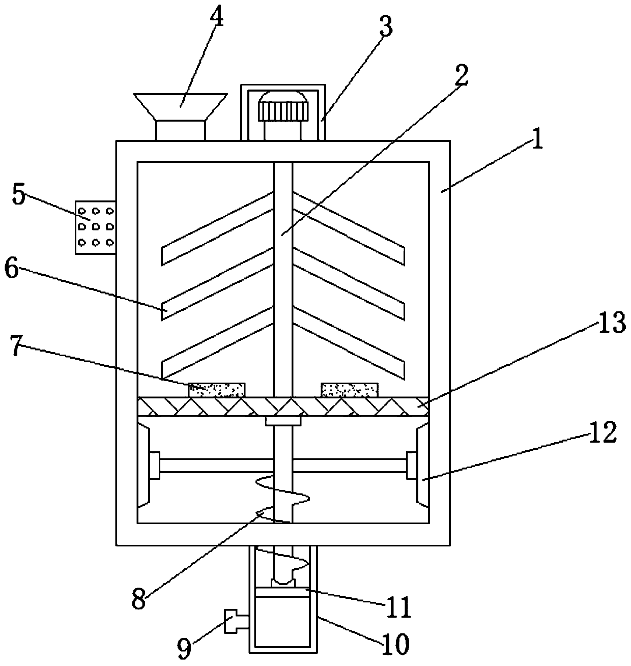
[0025] refer to Figure 1-2 , a melting device for curing agent coating production, comprising a box body 1, the inner walls of both sides of the box body 1 are connected with filter screens 13 by bolts, and the top outer wall of the filter screen 13 is provided with a heating block 7, the top of the box body 1 There is a fixing hole on the outer wall, and a feed hopper 4 is welded in the fixing hole. The top outer wall of the box body 1 is connected with a protective shell 3 by bolts, and the top inner wall of the protective shell 3 is connected with a motor by bolts. The outer wall of the output shaft of the motor is The rotating column 2 is welded, and the outer walls on both sides of the rotating column 2 are connected with stirring rods 6 by bolts.

[0026] Wherein, the bottom inner wall of the box body 1 is plugged with a feeding pipe 10, and the outer walls of both sides of the feeding pipe 10 are welded with fixing rods 11, and the outer wall of one side of the feeding...

Embodiment 2

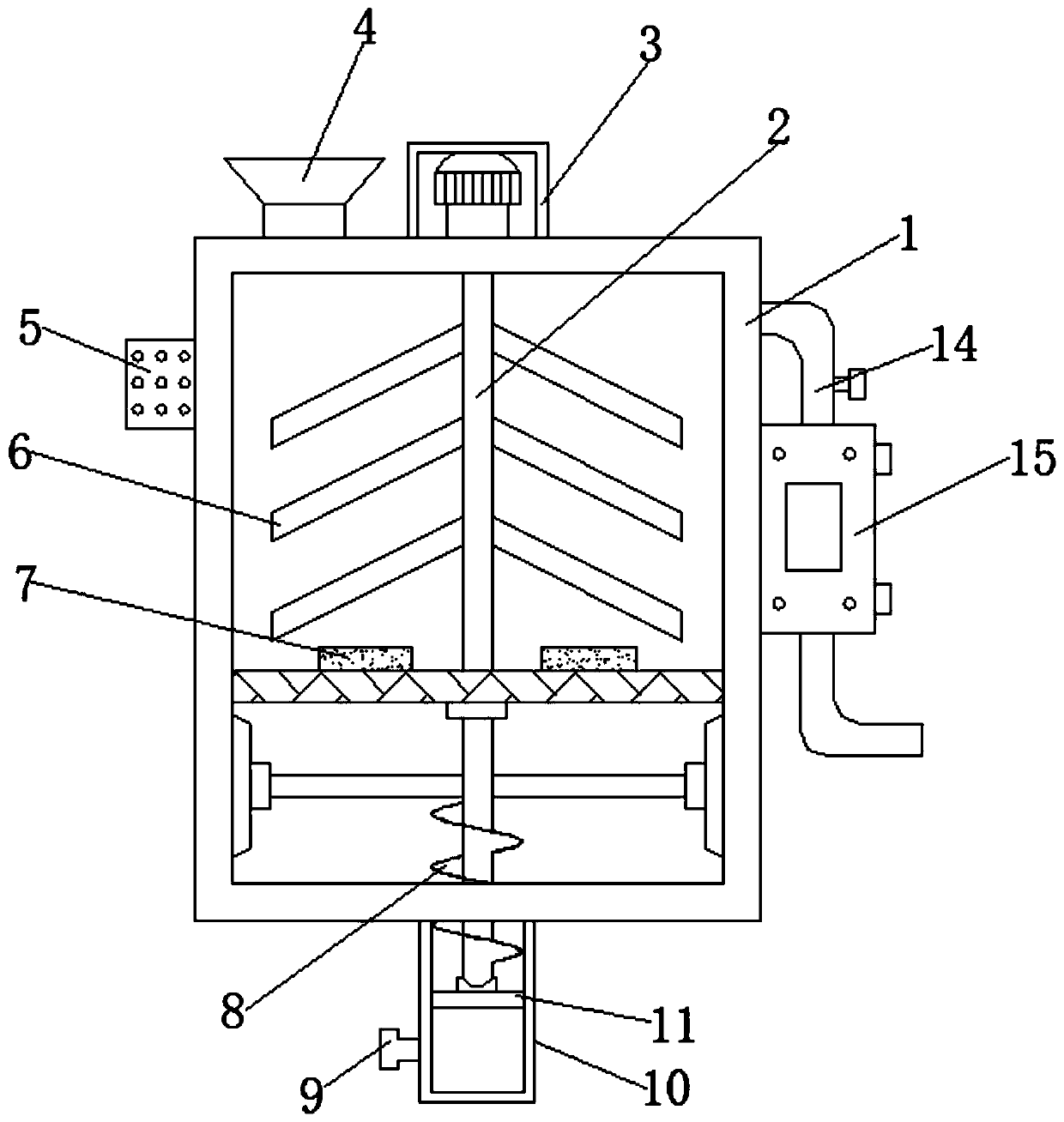
[0029] refer to image 3 , a melting device for curing agent paint production. Compared with Embodiment 1, the outer wall of one side of the box body 1 is connected with an air guide pipe 14, and one end of the air guide pipe 14 is connected with an air cleaner 15. The purifier 15 is connected to one side outer wall of the box body 1 by bolts.

[0030] Working principle: When in use, the staff puts the material into the box 1 through the feed hopper 4, melts the material through the heating block 7, and starts the motor at the same time, and the motor drives the rotating column 2 and the stirring rod 6 to rotate together to process the material. Stirring work improves the rate of material melting. When the device is performing melting work, open the control valve on the outer wall of the air guide pipe 14, and the waste gas generated during the melting process enters the air purifier 15 through the air guide pipe 14 to purify the waste gas. Avoid the direct discharge of exhau...


PUM


Abstract

The invention discloses a melting device for curing agent coating production, which comprises a box body, wherein filter screens are arranged on the inner walls of two sides of the box body, heating blocks are arranged on the outer wall of the top of the filter screens, a fixing hole is formed in the outer wall of the top of the box body, a feed hopper is arranged in the fixing hole, a protectiveshell is arranged on the outer wall of the top of the box body, a motor is arranged on the inner wall of the top of the protective shell, a rotating column is arranged on the outer wall of one end ofan output shaft of the motor, stirring rods are arranged on the outer walls of two sides of the rotating column, and a discharging pipe is inserted into the inner wall of the bottom of the box body. According to the invention, when the rotating column rotates, a propeller is driven to rotate, and materials in the box body can be discharged through the discharging pipe at this time, so that discharging work of people is facilitated, blockage of the discharging pipe is avoided, and materials adhered to the inner wall of the box body can be scraped off through the scraper, so that cleaning of workers is facilitated, and waste of resources is avoided.

Description

technical field [0001] The invention relates to the technical field of curing agent paint production, in particular to a melting device for curing agent paint production. Background technique [0002] The full name of the curing agent is p-hydroxybenzenesulfonic acid, also known as phenolsulfonic acid. This substance is mainly used for resin curing and is the most important additive in the acidic tin plating process. It also has the effect of acidic resin foaming and is used for organic intermediates. [0003] In the production process of curing agent coating, it is necessary to melt the material, and then after a series of processing, the finished curing agent coating can be obtained. The general melting device tends to stick to the inside of the melting device after melting the material, which not only brings great inconvenience to people's cleaning work, but also causes waste of resources and cannot meet the production needs of the factory. Therefore, need badly a kind o...

Claims


Application Information

Patent Timeline
Patent Type & Authority Applications(China)
IPC IPC(8): B01J6/00
CPCB01J6/005
Inventor 汪绍平
Owner 湖北汉耐尔新材料科技有限公司
Why Eureka
Try Eureka