
Deicing pantograph bow suitable for T-shaped rigid catenary system

A rigid contact and bow head technology, applied in the field of rail transit, can solve problems such as water seepage, excessive wear of deicing devices, and easy icing of rigid contact nets, so as to reduce violent shaking, avoid water accumulation and freezing, and avoid collapse of nets. effect of accident

Active Publication Date: 2020-01-10
SOUTHWEST JIAOTONG UNIV
View PDF6 Cites 0 Cited by
  • Summary
  • Abstract
  • Description
  • Claims
  • Application Information

AI Technical Summary

Problems solved by technology

[0004] Most of the existing rigid catenary use "I"-shaped bus bars to clamp the contact line. The humidity in the tunnel is high and water seepage occasionally occurs. Seepage water is easy to accumulate on the top of the bus bar, and this structure makes seepage flow to both sides and At the bottom line clamp; if the tunnel is in a low temperature environment for a long time, seepage and ice will wrap the entire busbar and contact wires, which will seriously affect the flow of the pantograph, and it will be difficult to remove if the ice is thick
[0005] At present, catenary deicing can be divided into artificial deicing, high current thermal deicing, natural passive anti-icing and other methods, but the efficiency of these deicing measures is extremely low; in France, the line running at a speed of less than 200km / h In the past, a deicing device similar to the pantograph was installed on the front end of the pantograph, but there are some problems in the existing deicing device: (1) The icing situation of the rigid catenary is more serious, and the thicker ice layer is difficult to remove , resulting in incomplete deicing and affecting the flow
(2) During the high-speed running of the train, the rigid impact of the deicing device and the ice coating will easily damage the rigid catenary, and at the same time cause serious deformation of the deicing device, and even detach from the ice layer to achieve the deicing effect
(3) Existing deicing devices are mainly used in flexible catenary. When used in rigid catenary, it is easy to cause the deicing device to wear too fast, and the regular replacement of the worn out deicing device consumes a lot of labor costs
(4) Severe shaking during the deicing process can easily halve the deicing effect, lack of fixing and guiding devices
[0006] Therefore, based on the background that some lines are located in alpine regions and pass through many tunnels, it is necessary to design a new type of rigid catenary and a supporting deicing device to solve the problem of icing and no effective deicing measures for the rigid catenary in the prior art. question

Method used


Image

  • Deicing pantograph bow suitable for T-shaped rigid catenary system
  • Deicing pantograph bow suitable for T-shaped rigid catenary system
  • Deicing pantograph bow suitable for T-shaped rigid catenary system

Examples


Embodiment Construction

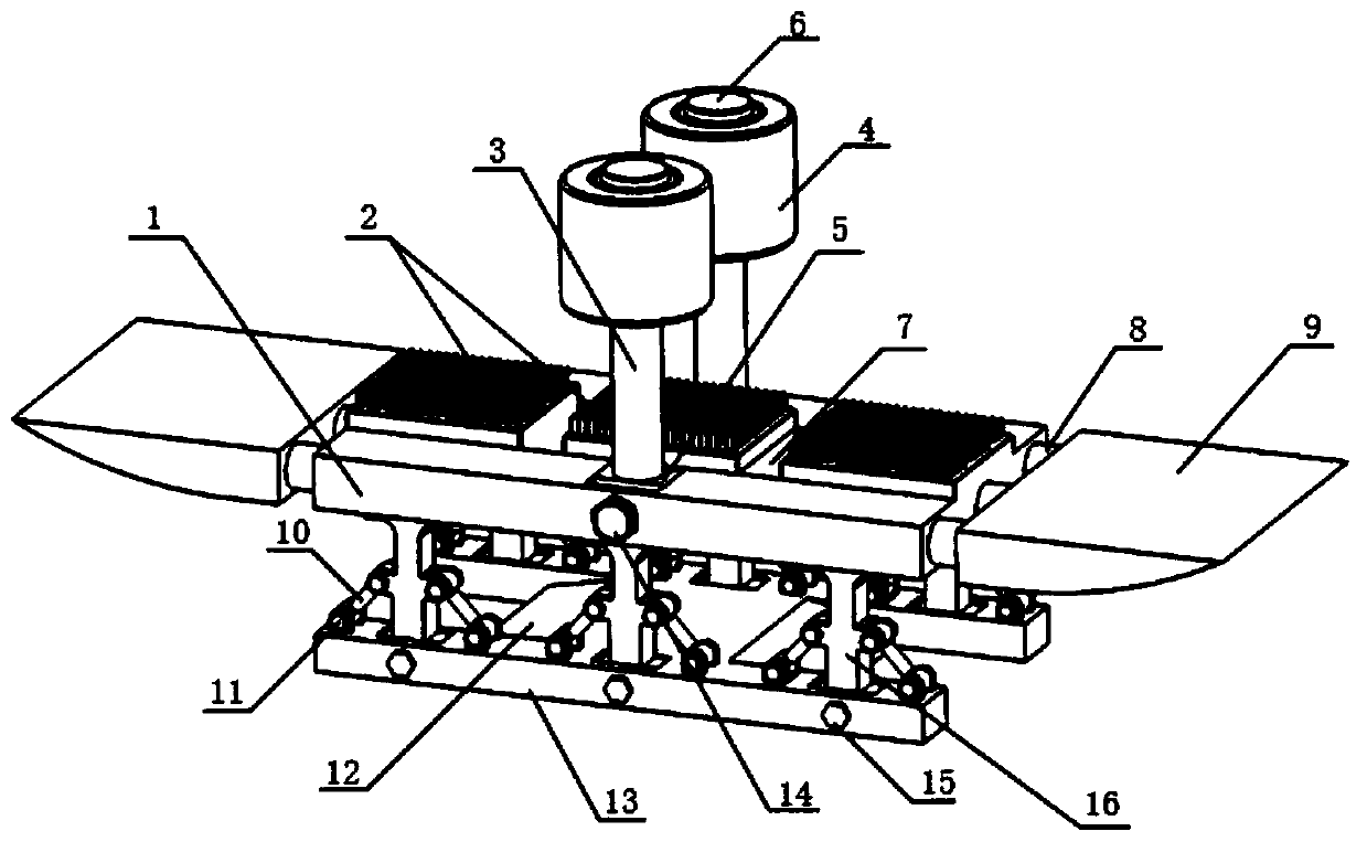
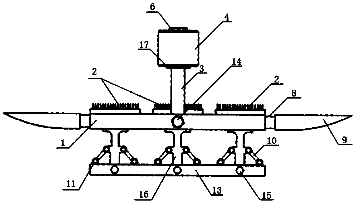
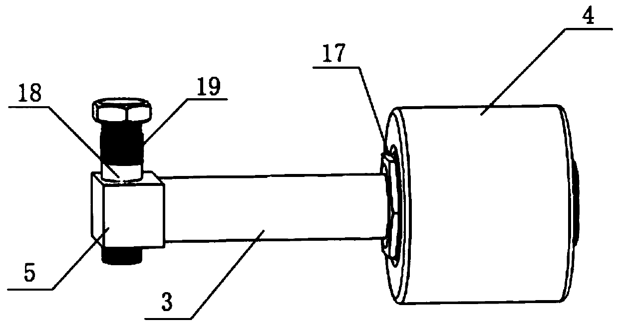
[0028] Figure 5 figure 1 It shows that a "T" type rigid contact current receiving device suitable for alpine regions and tunnels is composed of a "T" type rigid catenary and a deicing bow; the "T" type rigid catenary is composed of multiple suspension mechanisms and The bus bar 26 and the contact wire 29 are composed, wherein, the cross-sectional shape of the bus bar 26 is a "T" shape composed of a horizontal section and a vertical section, and the cutout at the bottom of the vertical section forms a pair of chucks, and the contact wire 29 The clamping bolt 27 and the clamping nut 28 are clamped on the chuck of the bus bar 26; the suspension mechanism is: T-bolts 23 are respectively fixed at both ends of the channel steel 20, and the tops of the two T-bolts 23 are used for fixing on On the inner wall of the tunnel, the insulator 21 is fixed on the bottom surface of the channel steel 20, the bus bar clamp 22 is fixed on the bottom of the insulator 21 by bolts, and the two end...


PUM


Abstract

A deicing pantograph bow suitable for a T-shaped rigid catenary system is characterized in that the structure of the deicing pantograph bow is that three deicing metal brushes are arranged on the topsurface of a supporting plate; deicing knives are fixed in front of and behind the supporting plate; more than one pairs of rollers are hinged to the supporting plate; two rows of supporting plate brackets are fixed on the bottom surface of the supporting plate, and each row is provided with three supporting plate brackets; the lower part of each bracket is movably inserted into a groove port in apantograph bow base and movably sleeves a bolt through a hole in each bracket; the bolts are screwed to the supporting plate brackets; and springs are correspondingly fixed between the two sides of each bracket and the pantograph bow base. The deicing pantograph bow suitable for the T-shaped rigid catenary system has the advantages that ices on the catenary system can be effectively shoveled, andthe current collection is stable.

Description

technical field [0001] The invention relates to the technical field of rail transit, in particular to a deicing device for a "T"-shaped rigid catenary suitable for alpine regions and tunnels. Background technique [0002] The catenary is unique to electrified railways. It is a special power supply line erected along the rails to provide electric energy for electric trains. As an outdoor power transmission system, it must withstand the influence of all natural conditions, such as wind, sun and rain. It must also withstand the impact of the pantograph on the catenary and the resulting vibration and fatigue. [0003] Overhead catenary is divided into rigid catenary and flexible catenary. Compared with flexible catenary, rigid catenary has certain advantages, such as small space occupation, no need to set anchor device, less parts, safety and reliability, etc. . The construction of railways in high cold and high-altitude mountainous areas requires the construction of many long...

Claims


Application Information

Patent Timeline
Patent Type & Authority Applications(China)
IPC IPC(8): B60L5/20B60L5/02
CPCB60L5/02B60L5/20
Inventor 肖嵩赖新安孟举叶智宗童梦园李玉航魏文赋吴广宁
Owner SOUTHWEST JIAOTONG UNIV
Learn More