Sewage treatment system reconstruction method

A sewage treatment system and sewage treatment technology, applied in biological water/sewage treatment, water/sludge/sewage treatment, biological treatment devices, etc., can solve problems such as rising construction costs, and achieve small footprint and sewage treatment capacity. The effect of speeding up the reconstruction period

Inactive Publication Date: 2020-01-10
中化学朗正环保科技有限公司
View PDF5 Cites 0 Cited by
  • Summary
  • Abstract
  • Description
  • Claims
  • Application Information

AI Technical Summary

Problems solved by technology

In addition, the long-term construction period will lead to an increase in construction costs

Method used


Image

  • Sewage treatment system reconstruction method
  • Sewage treatment system reconstruction method
  • Sewage treatment system reconstruction method

Examples


Embodiment 1

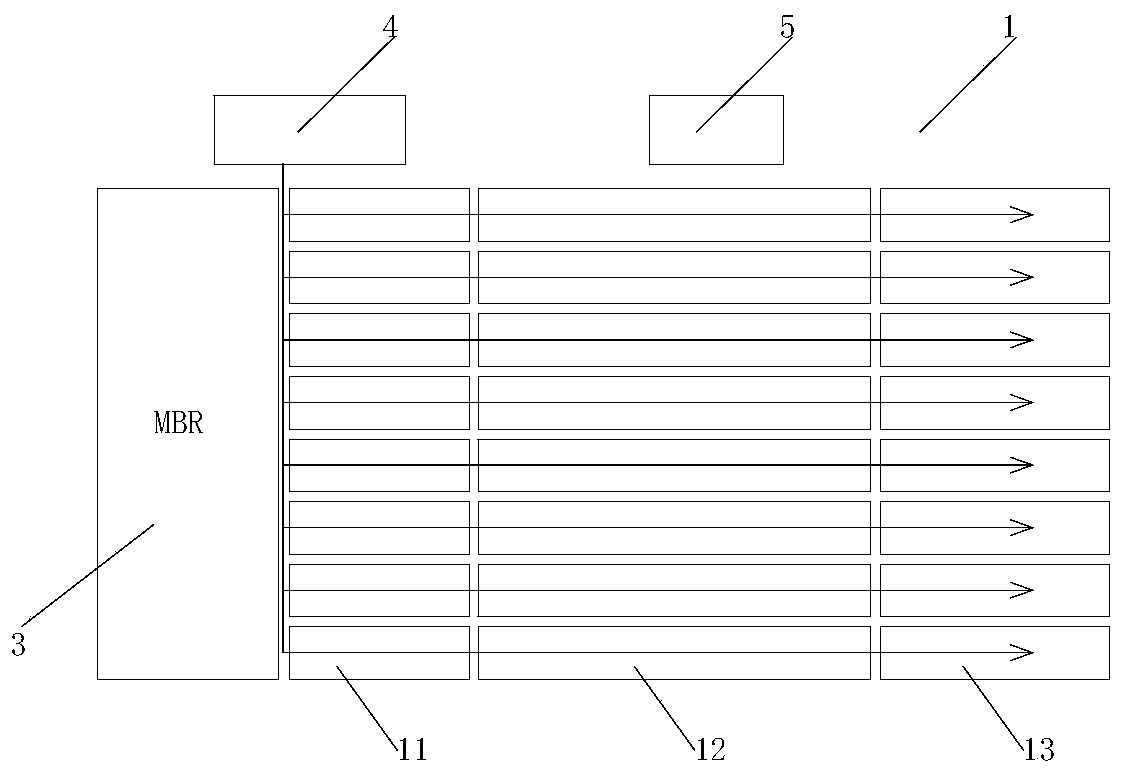
[0026] Example one, such as Figure 1 to Figure 4 Shown:

[0027] Such as figure 1 As shown, the MBR reaction tank 3 is correspondingly arranged at the side position of all the existing primary sedimentation tanks 11, and only the MBR reaction tank 3 is directly used for sewage treatment;

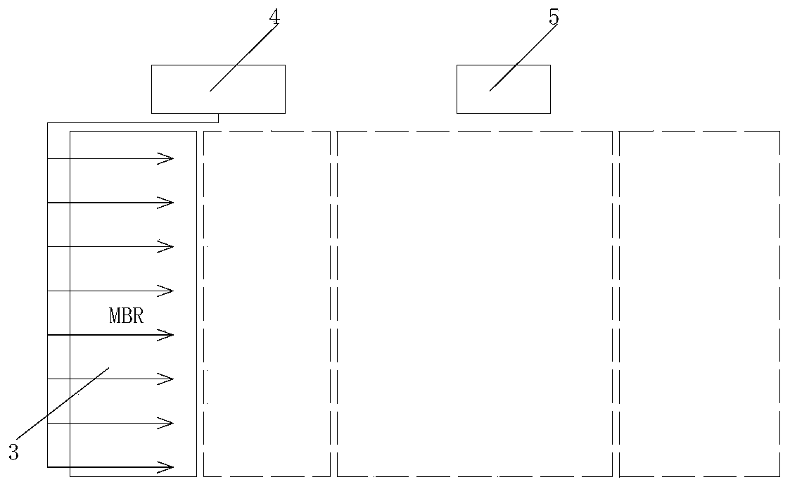
[0028] Such as figure 2 As shown, the existing primary sedimentation tank 11, the existing biological reaction tank 12 and the existing final sedimentation tank 13 are all removed;

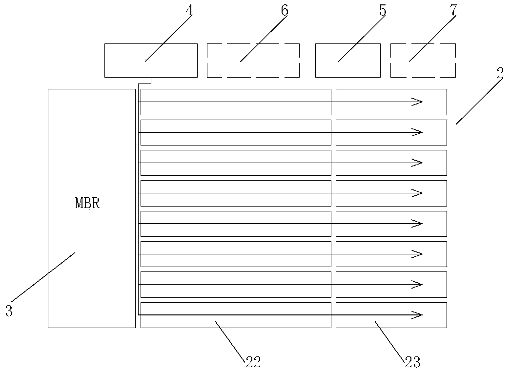
[0029] Such as image 3 As shown, the MBR reaction tank 3 is followed by successively constructing multiple new biological reaction tanks 22 and multiple new final sedimentation tanks 23; the MBR reaction tank 3 is stopped, and multiple newly established biological reaction tanks 22 and multiple new final sedimentation tanks are used. The sedimentation tank 23 is used for sewage treatment; in this step, the primary sedimentation tank is not used for sewage treatment temporarily, although part of the primary sedimenta...

Embodiment 2

[0031] Example two, such as Figure 5 to Figure 11 Shown:

[0032] Such as Figure 5 with Image 6 As shown, the MBR reaction tank 3 is correspondingly set at a side position of a part of the existing primary sedimentation tank 11, and the MBR reaction tank 3 and this part of the existing primary sedimentation tank 11 belong to the existing sewage treatment device 1 for sewage treatment; The existing primary sedimentation tank 11, the existing biological reaction tank 12 and the existing final sedimentation tank 13 of the remaining existing sewage treatment device 1 are all removed; as a further preferred solution, all the existing primary sedimentation tanks 11 are equally divided from the middle There are two groups, the MBR reaction tank 3 is correspondingly set beside the existing primary sedimentation tank 11 in one of them, and the two phases are demolished and constructed twice;

[0033] Such as Figure 7 As shown, a new initial sedimentation tank 21 was built at a position ...

Embodiment 3

[0036] Example three, such as Figure 12 to Figure 17 Shown:

[0037] Such as Picture 12 with Figure 13 As shown, the MBR reaction tank 3 corresponds to the side position of a set of existing sewage treatment devices 1 arranged on the outermost side of the sewage treatment system. The MBR reaction tank 3 and half of the existing sewage treatment devices 1 are used for sewage treatment; In the preferred solution, there are two MBR reaction tanks 3, and the two MBR reaction tanks 3 correspond to the side positions of the existing sewage treatment device 1 on both sides of the sewage treatment system.

[0038] Such as Figure 14 As shown, the existing primary sedimentation tank 11, the existing biological reaction tank 12, and the existing final sedimentation tank 13 of the remaining half of the existing sewage treatment device 1 are all removed, and then half of the new sewage treatment device 2 is built on site;

[0039] Such as Figure 15 with Figure 16 As shown, the MBR reaction ...


PUM


Abstract

The invention relates to the field of environmental protection engineering construction, and provides a sewage treatment system reconstruction method. The method adopts an MBR reaction tank as a transition device for treating sewage in the sewage treatment system reconstruction process. Compared with a conventional biological reaction tank, the MBR reaction tank has the advantages of small occupied area and high sewage treatment capacity, and can be built by only utilizing a small part of the occupied area beside the existing sewage treatment device. Sewage treatment in the reconstruction process is completed by utilizing the MBR reaction tank, so normal sewage treatment is not affected when the existing sewage treatment device is dismounted, disassembling of the sewage treatment device for many times is avoided, and the reconstruction period can be shortened; and after the MBR reaction tank is reconstructed, MBR parts in the MBR reaction tank can be disassembled, and the tank body ofthe MBR reaction tank can be reused as a part of the sewage treatment system.

Description

Technical field [0001] The invention belongs to the field of environmental protection engineering construction, and particularly relates to a method for rebuilding a sewage treatment system. Background technique [0002] The civil construction main body of the sewage treatment plant currently in use will exceed its 50-year standard service life. It is foreseeable that more and more sewage treatment plants will need to be fully rebuilt in the future. In the prior art, most sewage plants use standard activated sludge methods for sewage treatment. During the reconstruction, there are the following methods: 1. Rebuild a sewage treatment system on the redundant site next to the original sewage treatment system, but some sewage treatment plants do not have a large enough site; 2. Shut down the sewage treatment system alternately so that some of them are concentrated. , Another part is demolished and reconstructed, but the sewage treatment capacity of some sewage treatment plants is cl...

Claims


Application Information

Patent Timeline
Patent Type & Authority Applications(China)
IPC IPC(8): C02F3/12C02F3/30
CPCC02F3/12C02F3/301C02F2203/006Y02W10/10
Inventor 朱龙海于再基刘辛
Owner 中化学朗正环保科技有限公司
Why Eureka
Try Eureka