Rock wool fiberizing centrifuge

A cotton fiber-forming centrifuge, centrifugal roller technology, applied in glass manufacturing equipment, manufacturing tools and other directions, can solve the problems of inconvenient installation, high production and maintenance costs, achieve convenient connection and disassembly, ensure stability and service life, Improved sealing effect

Pending Publication Date: 2020-01-10
CHANGZHOU YINGLAI MACHINERY
View PDF0 Cites 2 Cited by
  • Summary
  • Abstract
  • Description
  • Claims
  • Application Information

AI Technical Summary

Problems solved by technology

Due to the different sizes of the roller body of the rock wool fiber centrifuge, each size of the roller body needs to be equipped with a corresponding type of glue spray ring, which is inconvenient to install, and when a nozzle on the glue spray ring is damaged, then Need to replace the entire glue spray ring, the production and maintenance costs are too high

Method used


Image

  • Rock wool fiberizing centrifuge
  • Rock wool fiberizing centrifuge
  • Rock wool fiberizing centrifuge

Examples


Embodiment 1

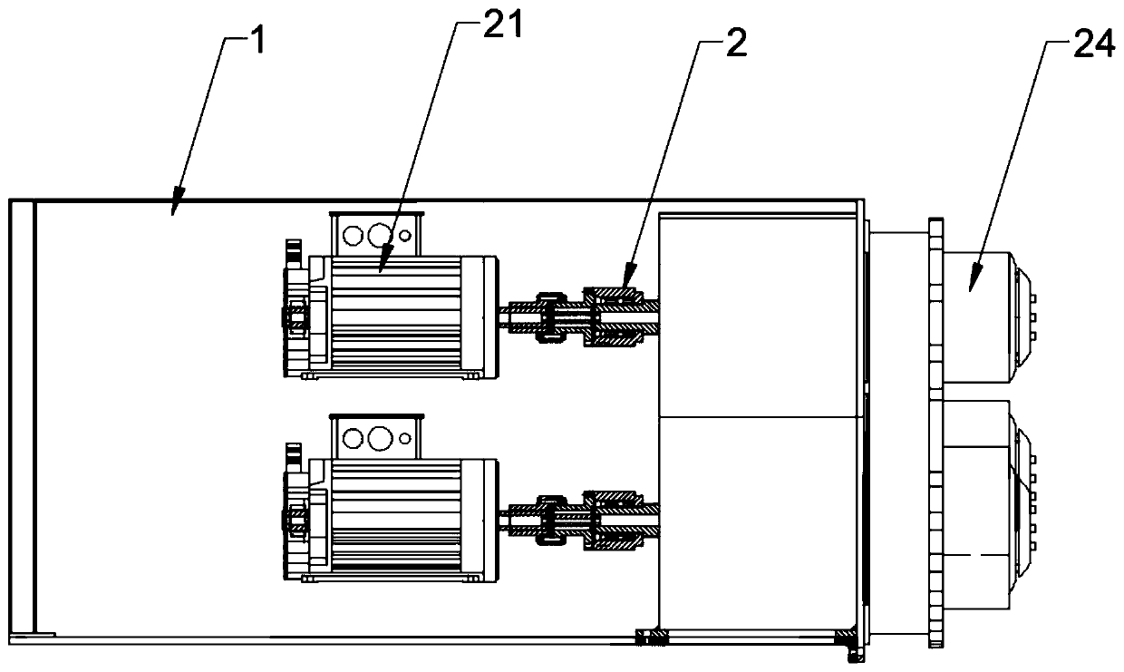
[0043] See figure 1 , the rock wool fiber-forming centrifuge of this embodiment includes a frame 1, a plurality of centrifugal roller assemblies 2 arranged on the frame 1, a split glue spray ring 3 arranged around the centrifugal roller assembly 2 provided, and a centrifugal Roller assembly 2 and the glue supply mechanism for the split glue spray ring.

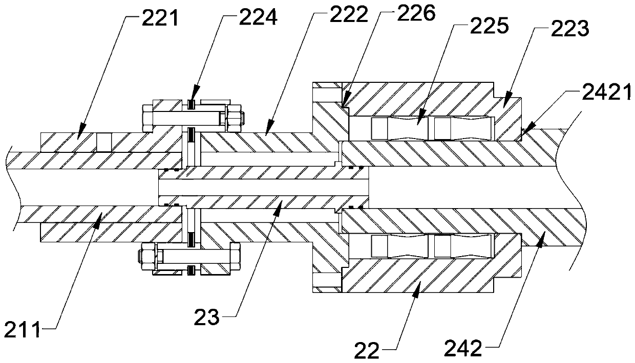
[0044] See figure 2 and image 3, The centrifugal roller assembly 2 includes a motor 21 , a coupling 22 , a connecting pipe 23 and a roller body 24 . The output shaft 211 of the motor 21 is a hollow shaft passing through the two ends of the motor 21, so glue can be fed from the output shaft 211 of the motor 21. The output shaft 211 of the motor 21 is fixedly connected with the roller body 24 through a coupling 22 .

[0045] The shaft coupling 22 includes a first shaft sleeve 221 , a second shaft sleeve 222 and a third shaft sleeve 223 fixedly connected by bolts in sequence. The first sleeve 221 and the third sleeve 223 a...

Embodiment 2

[0058] See Image 6 , this embodiment is basically the same as Embodiment 2, except that: the first sleeve 221 and the third sleeve 223 of the shaft coupling 22 of the centrifugal roller assembly 2 are respectively sleeved on the output shaft 211 of the motor 21 and the roller body 24; the sides of the first shaft sleeve 221 and the third shaft sleeve 223 are fixedly connected with the output shaft 211 of the motor 21 and the roller body 24 respectively by screws; between the first shaft sleeve 221 and the second shaft sleeve 222, and the Diaphragms 224 are disposed between the second bushing 222 and the third bushing 223 .


PUM


Abstract

The invention discloses a rock wool fiberizing centrifuge. The rock wool fiberizing centrifuge comprises a frame, a plurality of centrifuging roller assemblies arranged on the frame, a split type gluespraying ring arranged around the centrifuging roller assemblies, and a glue supply mechanism for supplying glue to the centrifuging roller assemblies and the split type glue spraying ring; every centrifuging roller assembly comprises a motor, a shaft coupling, a connecting tube and a roller body; the output shaft of the motor is a hollow shaft penetrating through two ends of the motor; the output shaft of the motor is fixedly connected with the roller body through the shaft coupling; the connecting tube is located in the shaft coupling, and two ends of the connecting tube are connected withthe output shaft of the motor and the roller body correspondingly; a glue spraying tube communicated with the connecting tube is arranged in the roller body; and the output shaft of the motor, the connecting tube and the glue spraying tube in the roller body form the glue channel of the centrifuging roller assembly. The defects of large occupied space in transmission and easy slipping of an original belt are fundamentally overcome, the size of the rock wool fiberizing centrifuge is reduced, and the yield of rock wool is increased.

Description

technical field [0001] The invention relates to a rock wool fiber-forming centrifuge. Background technique [0002] The rock wool fiber-forming centrifuge is the core equipment in the rock wool production line used to produce rock wool, and it is an important factor that determines the output and quality of rock wool. Because the roller body of the rock wool fiber-forming centrifuge needs to be glued, the existing centrifugal fiber-forming machines all use a belt as the transmission device, and each centrifugal roller is driven by a motor through the belt to rotate, since the motor is installed on the side of the centrifugal roller , so it not only makes the centrifuge bulky and inconvenient for hoisting and maintenance, but also when the speed increases, the multi-belt is easy to slip, which restricts the further increase of the speed of the centrifugal roller, thereby limiting the output of rock wool, and the use of multi-belt drive also makes the centrifuge The uneven fo...

Claims


Application Information

Patent Timeline
Patent Type & Authority Applications(China)
IPC IPC(8): C03B37/00
CPCC03B37/00
Inventor 曹磊潘建橹
Owner CHANGZHOU YINGLAI MACHINERY
Why Eureka
Try Eureka