Load bearing, thermal insulation and decoration integrated building component, forming mold and manufacturing method thereof

A technology for building components and forming molds, applied in building structures, molds, buildings, etc., can solve the problems of easy falling off of thermal insulation materials and decorative panels, complicated operating procedures, short service life, etc. The effect of improving the firmness

Pending Publication Date: 2020-01-10
SHENZHEN XINTIANNENG TECH DEV
0 Cites 0 Cited by

AI-Extracted Technical Summary

Problems solved by technology

However, this kind of building components is to use the mold to cast the main body of the component first, and then paste the decorative panel, or first paste the insulation material on the main body of the component, and then use the decorative panel to buckle the th...

Method used

(4) mold rod is inserted in the through hole of mould, pouring concrete, reinforced concrete, gypsum, fly ash, magnesium oxide, calcium carbonate, foamed cement, fo...

Abstract

The invention relates to the field of building materials, in particular to a load bearing, thermal insulation and decoration integrated building component, a forming mold and a manufacturing method thereof. The building component includes a component body and two decorative panels. The component body includes a top surface, a bottom surface and left and right side faces, and the two decorative panels are located on the left and right side faces of the component body. At least one side edge of each decorative panel is provided with a hook bending towards the side of the component body, or/and the side, close to the component body, of each decorative panel is fixedly provided with at least one connection member; a certain included angle is formed between each connection member and the corresponding decorative panel, the other end of each connection member extends into the component body, and the decorative panels are connected with the component body through the connection members. By means of the building component, the connection members are used for realizing connection between the decorative panels and the component body, the connection members extend into the component body, thetail ends of the connection members are provided with claw structures, and the axial resistance borne by the connection members can be increased; and compared with prior pasting manner, the connecting manner is firmer, and the decorative panels are not prone to falling off.

Application Domain

Technology Topic

Image

  • Load bearing, thermal insulation and decoration integrated building component, forming mold and manufacturing method thereof
  • Load bearing, thermal insulation and decoration integrated building component, forming mold and manufacturing method thereof
  • Load bearing, thermal insulation and decoration integrated building component, forming mold and manufacturing method thereof

Examples

  • Experimental program(3)
  • Effect test(1)

Example Embodiment

[0043] Example 1
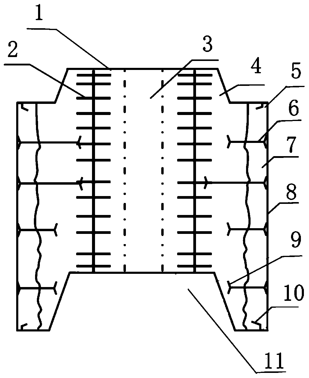
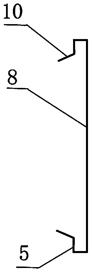
[0044] A load-bearing thermal insulation and decoration integrated building component, such as figure 1 As shown, it includes a component body 1 and two decorative panels 8 located on the left and right sides of the component body. like image 3As shown, the upper and lower edges of the two decorative panels 8 are provided with return hooks 5 that are bent toward the side of the main body of the component, and the end of the return hook 5 is inclined with a filler drainage plate 10, and the extension surface of the filler drainage plate 10 is 60 degrees from the decorative panel. angle. A number of connectors 6 with claws 9 at both ends are vertically placed on the decorative panel 8 near the main body of the component, and the claws at both ends of the connectors may also be V-shaped (such as Figure 4 shown), arc (such as Figure 5 shown) or a geometric back hook (such as Image 6 shown). One end of the connecting piece 6 is bonded to the decorative panel 8 through the gelling thermal insulation material 7 , and the other end extends into the component main body 1 . The connecting piece 6 is made of metal, plastic, wood or synthetic material. The main body of the component is cast by one or more of concrete, gypsum, fly ash, magnesium oxide, calcium carbonate, foamed ceramics and synthetic resin. The component main body 1 is provided with a reinforcement cage 2, and the ends of some of the longer connectors are connected to the reinforcement cage by tying. The component main body 1 is provided with a first groove 11 at the bottom and a first protrusion 4 at the top. The size of the first protrusion 4 and the first groove 11 are matched to realize stacking of components. The component main body 1 is also provided with up and down through holes 3 for installing pipelines.

Example Embodiment

[0045] Example 2
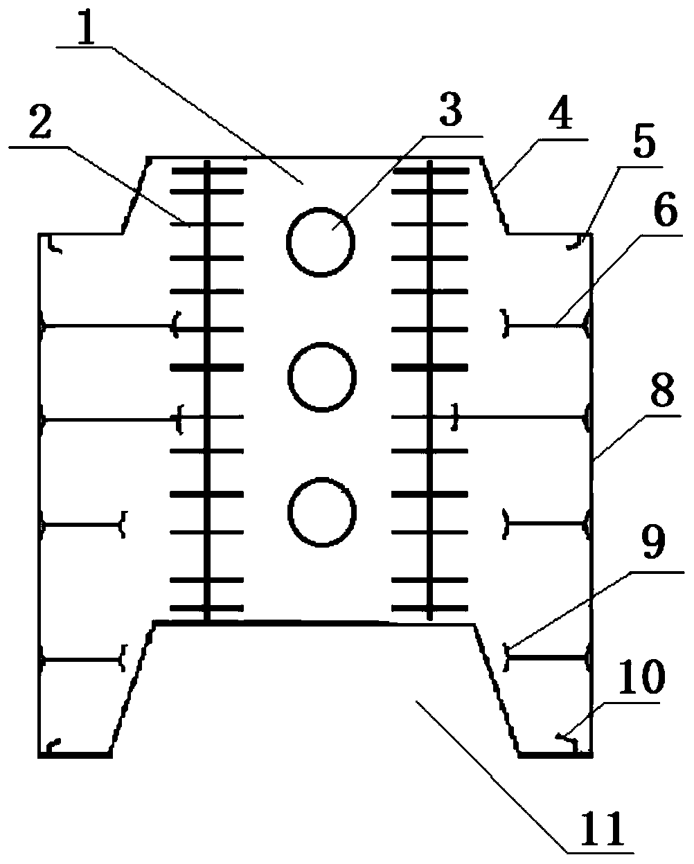
[0046] A load-bearing thermal insulation and decoration integrated building component, such as figure 2 As shown, it includes a component body 1 and two decorative panels 8 located on the left and right sides of the component body. like image 3 As shown, the upper and lower edges of the two decorative panels 8 are provided with return hooks 5 that are bent toward the side of the main body of the component, and the end of the return hook 5 is inclined with a filler drainage plate 10, and the extension surface of the filler drainage plate 10 is 60 degrees from the decorative panel. angle. A number of connectors 6 with claws 9 at both ends are vertically placed on the decorative panel 8 near the main body of the component, and the claws at both ends of the connectors may also be V-shaped (such as Figure 4 shown), arc (such as Figure 5 shown) or a geometric back hook (such as Image 6 shown). One end of the connector 6 is bonded to the decorative panel 8 , and the other end extends into the component body 1 . The connecting piece 6 is made of metal, plastic, wood or synthetic material. The main body of the component is made of foamed cement. The component main body 1 is provided with a reinforcement cage 2, and the ends of some of the longer connectors are connected to the reinforcement cage by tying. The component main body 1 is provided with a first groove 11 at the bottom and a first protrusion 4 at the top. The size of the first protrusion 4 and the first groove 11 are matched to realize stacking of components. The component main body 1 is also provided with a hole 3 that passes through the front and rear for installing the pipeline.

Example Embodiment

[0047] Example 3
[0048] A molding die for a building component integrated with load-bearing, thermal insulation and decoration, such as Figure 7 As shown, there are several mold baffles 12 arranged in parallel and spaced apart. The left and right sides of the mold baffle 12 are provided with a plurality of positioning strips 18 at intervals. The positioning strips are detachably connected to the mold baffle, and the positions of the positioning strips are set according to the size of the processed component. The cross section of the positioning bar can be trapezoidal, rectangular, triangular or circular. The positions of the positioning strips on the opposite sides of the adjacent mold baffles correspond to each other, and the two ends of the mold head are provided with positioning grooves that match the shape of the positioning strips. The middle of the front side of the die head is provided with a second protrusion 16, and the left and right edges of the front side are respectively provided with card grooves 14 that match the hook portion of the decorative panel in Example 1. The middle of the rear side of the die head is provided with a second groove 15, and the left and right edges of the rear side are respectively provided with card grooves 14 that match the hook portion of the decorative panel in Example 1. When installing the decorative panel, insert the decorative panel into the mold along the slot to ensure that the decorative panel is placed in place, thereby ensuring that the dimensions of the building components are consistent. The die head is provided with a plurality of longitudinally arranged through holes 17 for inserting the die rods and forming holes on the building components during pouring.

PUM

no PUM

Description & Claims & Application Information

We can also present the details of the Description, Claims and Application information to help users get a comprehensive understanding of the technical details of the patent, such as background art, summary of invention, brief description of drawings, description of embodiments, and other original content. On the other hand, users can also determine the specific scope of protection of the technology through the list of claims; as well as understand the changes in the life cycle of the technology with the presentation of the patent timeline. Login to view more.

Similar technology patents

Mosaic instrument control screen

Owner:杭州邦辉自动化工程技术有限公司 +1

Connecting and fixing device

PendingCN110966291AStrong connectionNot easy to shake relativelyFurniture joiningFastenerRetainer (device)
Owner:广东跃居家居科技有限公司

Classification and recommendation of technical efficacy words

  • Strong connection
  • Not easy to fall off

Sealed small low-impact release screw bolt

InactiveCN101875404AReduce shockStrong connectionCosmonautic component separationPistonMissile
Owner:BEIJING INSTITUTE OF TECHNOLOGYGY

Ball-and-socket joint

InactiveUS20060182491A1Strong connectionGood lockCouplings for rigid shaftsBellowsEngineeringBall and socket joint
Owner:TRW AUTOMOTIVE GMBH

Cellular heterogeneous network resource allocation method based on game theory

InactiveCN107864512ASatisfy traffic demandStrong connectionPower managementResource assignmentDynamic resource
Owner:NANJING UNIV OF POSTS & TELECOMM
Why Eureka
Try Eureka