Hydraulic system for manual emergency lifting of whole box hopper

A technology of hydraulic system and box material, which is applied to the safety of fluid pressure actuating system, fluid pressure actuating device, servo motor, etc. Maintenance and other problems, to ensure safety and efficiency, ensure the safety of life and property, and facilitate timely hoisting and transfer.

Pending Publication Date: 2020-01-10
FUJIAN LONGMA ENVIRONMENTAL SANITATION EQUIP
View PDF0 Cites 0 Cited by
  • Summary
  • Abstract
  • Description
  • Claims
  • Application Information

AI Technical Summary

Problems solved by technology

This working mode: 1. Since the location and time of the failure of the power system cannot be predicted in advance, at the same time, the probability of failure of the power system of the hopper at any point of its trajectory is the same
2. The power bin equipped with a power system is often arranged at a certain part of the movement path of the hopper swing arm (considering the volume of the storage bin and compression bin and the convenience of installation and maintenance of the power system, the power bin is generally not arranged at the position where the hopper is raised to its position ), so when the power system fails, the swing arm of the hopper may block the power bin door, making it impossible to pull out the power system for troubleshooting and repair
3. If the oil pipe of the hopper oil cylinder is removed and the position of the hopper is changed by external force or gravity, due to the heavy weight of the hopper, it may cause regeneration accidents that endanger the personal safety of maintenance personnel.
4. When the fault problem is relatively large and cannot be eliminated on site and needs to be taken to the maintenance factory for troubleshooting, if the hopper is not in the position of rising, it will block the lifting ring of the overall box, so that the hook arm truck cannot be hooked to the lifting ring for transfer

Method used


Image

  • Hydraulic system for manual emergency lifting of whole box hopper

Examples


Embodiment Construction

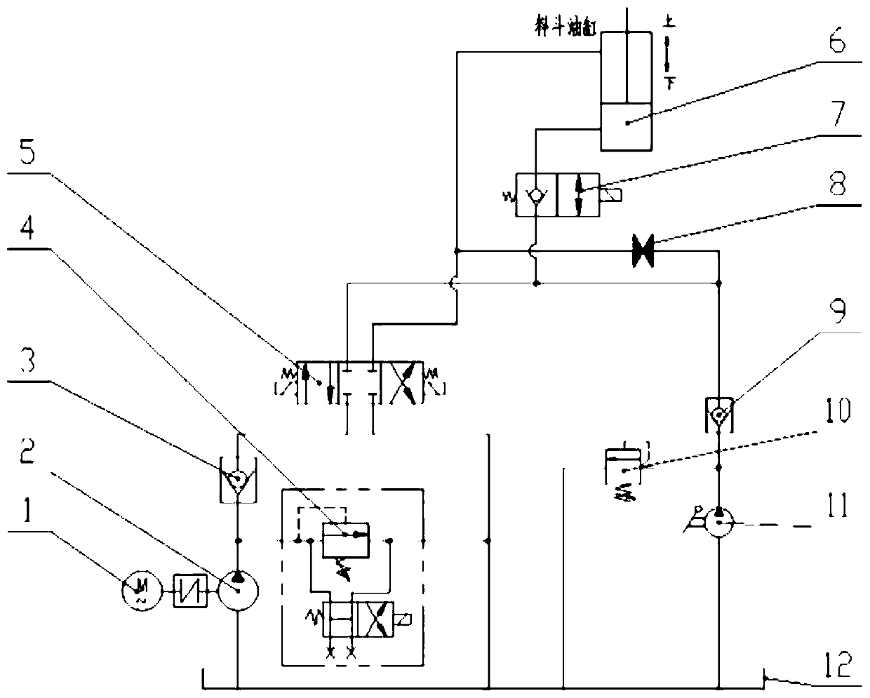
[0022] Such as figure 1 As shown, the hydraulic system with manual emergency lifting of the integrated box hopper of the present invention includes a motor 1, a hydraulic pump 2, a three-position four-way O-type electromagnetic reversing valve 5, a first one-way valve 3, and a second one-way valve 9 , two-position two-way electromagnetic reversing valve 7, hopper cylinder 6, high-pressure ball valve 8, manual pump 11 and fuel tank 12;

[0023] The motor 1 drives the hydraulic pump 2 to work;

[0024] The oil suction port of the hydraulic pump 2 is connected with the oil tank 12 through a pipeline, the pressure oil port of the hydraulic pump 2 is connected with the oil inlet of the first one-way valve 3 through the pipeline, and the oil outlet of the first one-way valve 3 passes through The pipeline is connected to the P port of the three-position four-way O-type electromagnetic reversing valve 5, the T port of the three-position four-way O-type electromagnetic reversing valve...


PUM


Abstract

The invention discloses a hydraulic system for manual emergency lifting of a whole box hopper. The system comprises a motor, a hydraulic pump, a three-position four-way O-shaped electromagnetic reversing valve, a first one-way valve, a second one-way valve, a two-position two-way electromagnetic reversing valve, a hopper oil cylinder, a high-pressure ball valve, a manual pump and an oil tank. Thehydraulic system has the following characteristics that 1, under the normal working condition, when a power source suddenly breaks down, the hopper can be guaranteed to be safe and not to decline sharply, and the personal safety is not endangered; 2, when a power system fails, the hopper can undergo manual emergency lifting conveniently, so that the fault can be eliminated in time, and the garbageoperation efficiency is ensured; 3, a hook arm vehicle can be guaranteed to conveniently and timely perform hoisting and transporting when the fault is large and a whole box needs to be transported to a maintenance factory for overhaul; 4, the hopper can rapidly and safely undergo manual emergency lifting, and the safety and efficiency of maintenance are ensured; and 5, the safety of life and property when a rubber pipe is burst is guaranteed.

Description

technical field [0001] The invention relates to the field of hydraulic systems, in particular to a hydraulic system with manual emergency lifting of an integral box hopper. Background technique [0002] At present, the integrated garbage compression bins of the domestic garbage compression category do not have a manual emergency lifting system for the hopper. This working mode: 1. Since the position and time of failure of the power system cannot be predicted in advance, the probability of failure of the power system of the hopper at any point of its trajectory is the same. 2. The power bin equipped with a power system is often arranged at a certain part of the movement path of the hopper swing arm (considering the volume of the storage bin and compression bin and the convenience of installation and maintenance of the power system, the power bin is generally not arranged at the position where the hopper is raised to its position ), so when the power system fails, the hopper ...

Claims


Application Information

Patent Timeline
Patent Type & Authority Applications(China)
IPC IPC(8): F15B20/00F15B11/08
CPCF15B11/08F15B20/005F15B2211/8636
Inventor 李基锋张庆明刘玮陈玮烨张宗锋张福燕林亮张德伟许顺林
Owner FUJIAN LONGMA ENVIRONMENTAL SANITATION EQUIP
Why Eureka
Try Eureka