
Anti-blocking soot-blowing device for waste incinerating boiler cyclone separator

A cyclone separator and waste incineration technology, which is applied in the field of boiler soot blowing device, can solve the problem of high temperature of dust accumulation or coke hanging in the separator, and achieve the effect of preventing a large amount of dust accumulation

Active Publication Date: 2020-01-10
武汉市绿色环保能源有限公司
View PDF9 Cites 0 Cited by
  • Summary
  • Abstract
  • Description
  • Claims
  • Application Information

AI Technical Summary

Problems solved by technology

Although the economic loss caused by this treatment method is small, because the temperature of dust accumulation or coke hanging inside the separator is very high, generally reaching about 950°C, and there is a large amount of fine dust inside the separator, during the dredging process, There are major personal, equipment, and environmental safety hazards
After the cleaning is completed, the boiler will be blocked again after running for about 15 days and needs to be reprocessed

Method used


Image

  • Anti-blocking soot-blowing device for waste incinerating boiler cyclone separator
  • Anti-blocking soot-blowing device for waste incinerating boiler cyclone separator
  • Anti-blocking soot-blowing device for waste incinerating boiler cyclone separator

Examples


Embodiment Construction

[0020] The present invention will be further described below in conjunction with the accompanying drawings and examples.

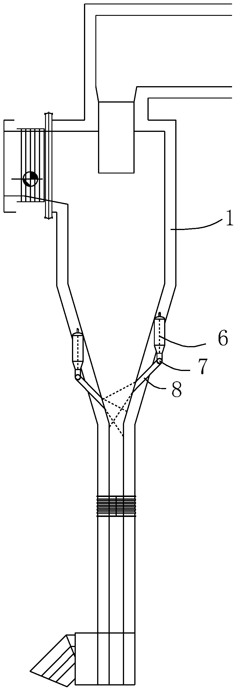
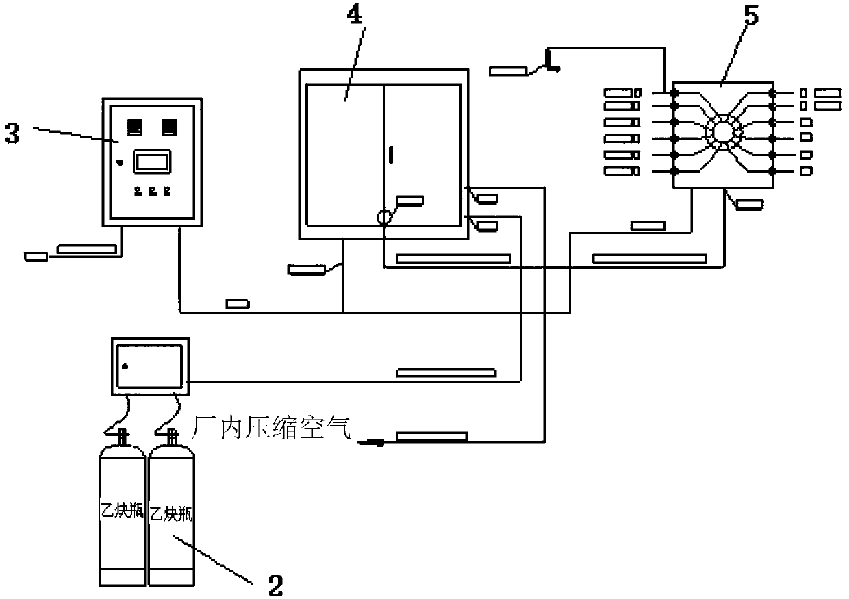
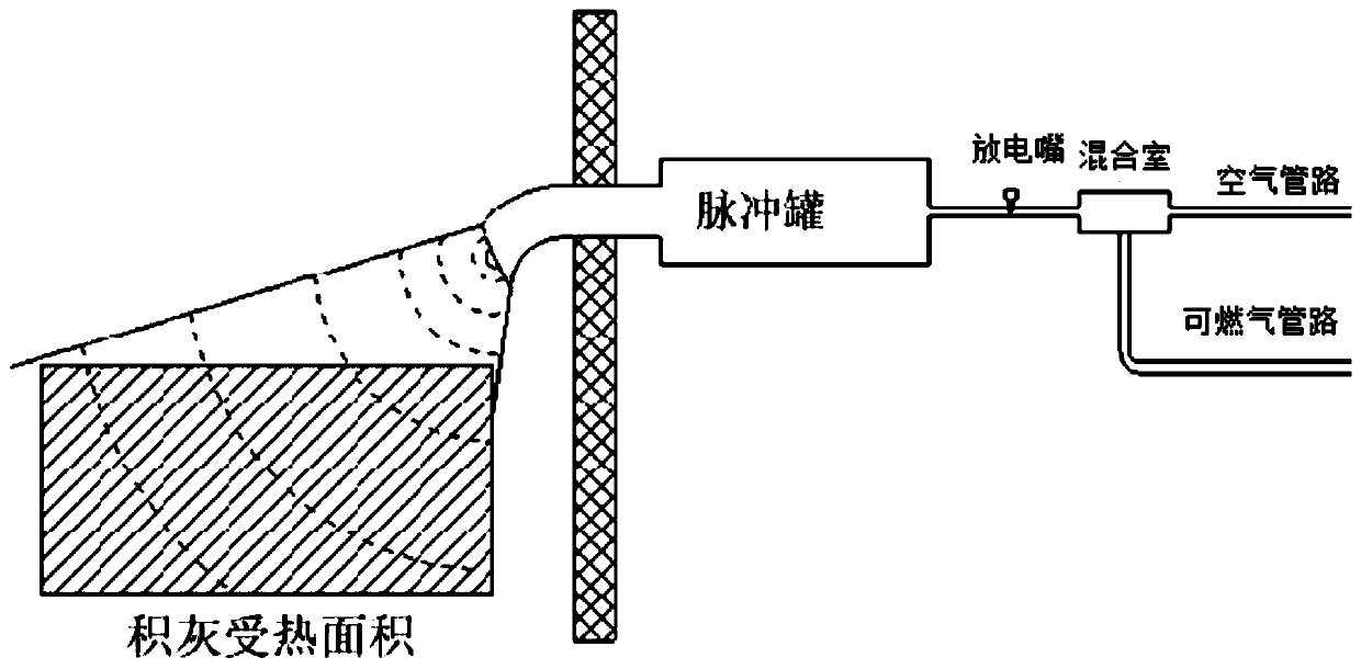
[0021] figure 1 , figure 2 , image 3 Among them, an anti-blocking soot blowing device for a cyclone separator of a waste incineration boiler, including a soot blower, at least one set of soot blowers, preferably two to eight sets, and the best of both, the soot blower is connected to the waste incineration boiler cyclone On the separator; the soot blower includes the gas source part, flow regulating cabinet, gas guiding ignition cabinet, control cabinet, pulse tank and soot blowing pipe, one end of the soot blowing pipe is connected to the pulse tank, and the other end passes through the outer wall of the separator and enters the inner Cavity, the output end of the gas-guiding ignition cabinet is connected with the pulse tank, the inlet end of the gas-guiding ignition cabinet is connected with the flow regulating cabinet, and the signal end of the cont...


PUM

PropertyMeasurementUnit
thicknessaaaaaaaaaa

Abstract

The invention provides an anti-blocking soot-blowing device for a waste incinerating boiler cyclone separator. The anti-blocking soot-blowing device for the waste incinerating boiler cyclone separatorcomprises soot blowers. One or more sets of soot blowers are arranged and connected to the waste incinerating boiler cyclone separator. Each soot blower comprises a gas source portion, a flow regulation cabinet, a gas guide ignition cabinet, a control cabinet, a pulse tank and a soot blowing pipe. One end of the soot-blowing pipe is connected with the pulse tank, and the other end of the soot blowing pipe penetrates through the outer wall of the separator and enters the inner cavity. The output end of the gas guide ignition cabinet communicates with the pulse tank. The gas input end of the gas guide ignition cabinet communicates with the flow regulation cabinet. The signal end of the control cabinet is connected with the flow regulation cabinet and the signal end of the gas guide ignitioncabinet. The soot blowers are divided into high position soot blowers and low position soot blowers. The cone horn mouth of the separator is covered by the working area of the low position sot blowers, injection orifices of the low position soot blowers is covered by the working area of the high position soot blowers, and opposite-direction staggered arrangement is formed. Through the impact force generated by the soot blowers, the boiler separator cone and wall surface are swept through blowing, and the phenomena that a large amount of soot is accumulated on the separator, soot transportation of a return feeder vertical pipe is not smooth and tar sticks are prevented from occurring.

Description

technical field [0001] The invention relates to a boiler soot blowing device, in particular to an anti-blocking soot blowing device for a cyclone separator of a garbage incineration boiler. Background technique [0002] In recent years, as the form of environmental protection has become more and more serious, in order to meet the requirements of environmental protection flue gas emission, the waste disposal equipment and boiler incineration system have undergone multiple transformations, and many parameters and operating conditions have deviated from the original design values. It has achieved great results in environmental protection and stable discharge, but there are frequent problems in the combustion process of the boiler, such as coke hanging in the separator, ash accumulation in the cone, and blockage of the return feeder, which seriously affect the economical and stable operation of the boiler. There are only two general ways to deal with such failures: [0003] 1. ...

Claims


Application Information

Patent Timeline
Patent Type & Authority Applications(China)
IPC IPC(8): F23J3/00B01D45/18B01D45/12
CPCB01D45/12B01D45/18F23J3/00
Inventor 黄卫鹏王镭吕志平熊超姜龙夏小栋熊伟
Owner 武汉市绿色环保能源有限公司
Learn More