

Multifunctional low-dimensional photoelectric material detection platform
An optoelectronic material, multi-functional technology, applied in analyzing materials, testing material strength using stable bending force, testing material strength using stable tension/pressure, etc., can solve the problem of increased workload, solar panel stretching, The bending strength test bench of the solar panel cannot be used for tensile test and other problems, so as to achieve the effect of uniform force and improved efficiency
- Summary
- Abstract
- Description
- Claims
- Application Information
AI Technical Summary
Problems solved by technology
Method used
Image

Examples
Embodiment 1
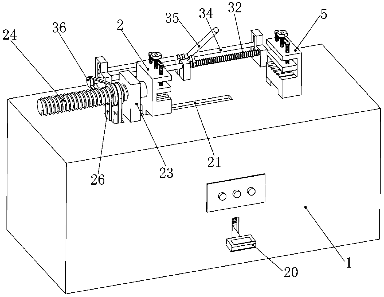
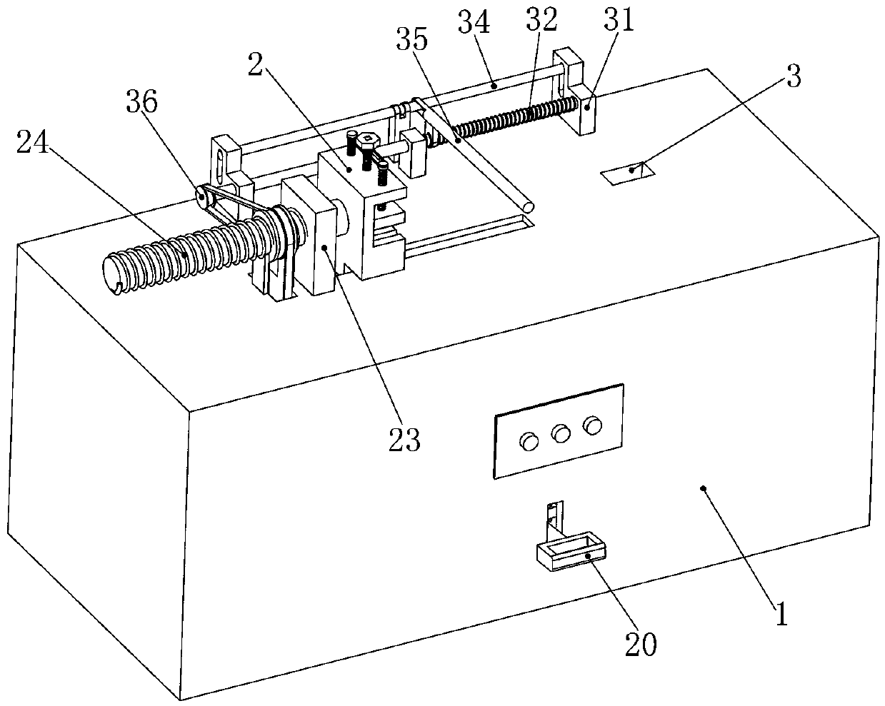
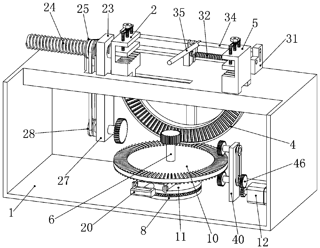
[0031]Embodiment 1, the present invention is a multi-functional low-dimensional photoelectric material detection platform, including a base 1 with a hollow interior, and the base 1 provides a fixed foundation for the subsequent structure. It is characterized in that the left end of the top surface of the base 1 is fixedly installed with a first clip Hand 2, the first clamping hand 2 is used to clamp the solar panel, the first clamping hand 2 is fixedly installed on the top surface of the base 1 near the left end, and can be fixed by bolts or other fixing methods. The top surface of the base 1 The right end is provided with a rack groove 3, the rack groove 3 is close to the right end of the top surface of the base 1 and runs through the top surface of the base 1, an arc rack 4 is slidably installed in the rack groove 3, and the arc rack 4 The teeth on the top are helical teeth, and the arc rack 4 can slide up and down in the rack groove 3. The end of the arc rack 4 located above...
Embodiment 2
[0032] Embodiment 2, on the basis of Embodiment 1, grooves 13 are formed on the corresponding sides of the first gripper 2 and the second gripper 5, and the first gripper 2 faces the side of the second gripper 5 There is a groove 13 on one side, and the solar panel is clamped in the groove 13. The side of the second gripper 5 facing the first gripper 2 also has a groove 13, and the two grooves 13 are respectively A pressing plate 14 is installed to slide up and down, and the pressing plate 14 can slide up and down in the groove 13. When the solar panel is placed in the groove 13, sliding the pressing plate 14 downward can fix the solar panel in the first position. On the gripper 2 and the second gripper 5, a plurality of fastening bolts 15 respectively penetrating through the top surfaces of the first gripper 2 and the second gripper 5 are installed on the top surfaces of the two pressing plates 14, The fastening bolts 15 can rotate on the pressing plate 14, and the tops of th...
Embodiment 3
[0033] Embodiment 3, on the basis of Embodiment 1, an annular groove 19 is formed on the outer surface of the sleeve 9, and an annular groove 19 is formed on the outer surface surrounding the sleeve 9. The front inner wall of the base 1 A conversion handle 20 that runs through the front end of the base 1 is rotated on the top, and a vertical handle installation hole is opened on the front end of the base 1. The conversion handle 20 is hinged on the front inner wall of the base 1 through the handle installation hole. One end of the conversion handle 20 located in the base 1 is bifurcated and a runner is installed for rotation respectively. The runners are respectively placed in the annular groove 19, and the outer diameters of the two runners are smaller than the width of the annular groove 19. Pulling the conversion handle 20 up and down can drive the sleeve 9 to slide up and down on the rotating rod 6, and the sleeve 9. When turning, the two runners at the end of the conversi...
PUM
 Abstract
Description
Claims
Application Information