Micro-seismic sensor taking and placing device with strain gauge bonding structure and using method thereof

A technology of microseismic sensors and pick-and-place devices, which is applied in the direction of measuring devices, seismic signal receivers, instruments, etc., can solve the problems of extended construction period, time-consuming and labor-intensive installation process, high economic cost, etc., and achieve the effect of reducing economic cost

Active Publication Date: 2020-01-10
HEFEI UNIV OF TECH
View PDF8 Cites 5 Cited by
  • Summary
  • Abstract
  • Description
  • Claims
  • Application Information

AI Technical Summary

Problems solved by technology

This method has the following disadvantages: 1) The sensor is not recyclable, resulting in high economic costs; 2) After pouring, if the sensor is found to have no signal or the signal is not good, it cannot be checked; 3) It takes a long period for the cement slurry to solidify after pouring, which will lead to poor construction. The deadline is extended; 4) The installation process is time-consuming and laborious, requiring a series of professional grouting equipment and grouting personnel, requiring a lot of labor
[0005] At the same time, the existing installation method of microseismic sensor mainly considers placing the microseismic sensor at the predetermined depth of the hole to receive elastic wave and stress wave signals, and does not consider monitoring the strain of the hole wall.

Method used


Image

  • Micro-seismic sensor taking and placing device with strain gauge bonding structure and using method thereof
  • Micro-seismic sensor taking and placing device with strain gauge bonding structure and using method thereof
  • Micro-seismic sensor taking and placing device with strain gauge bonding structure and using method thereof

Examples


Embodiment Construction

[0049] The present invention will be further described below in conjunction with accompanying drawing:

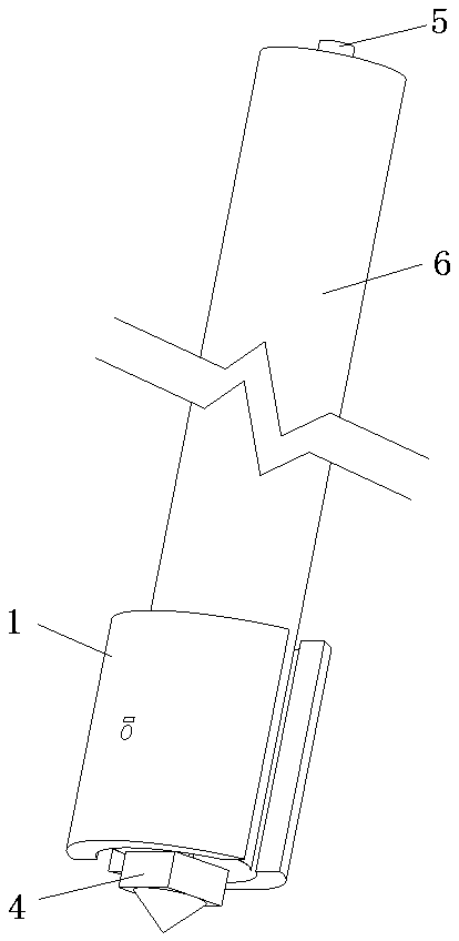
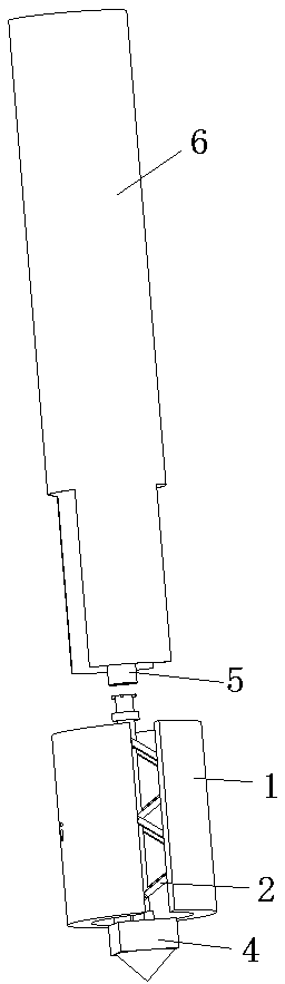
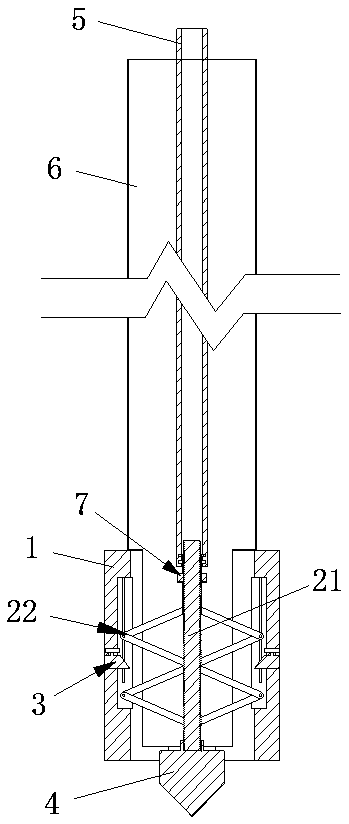
[0050] Such as figure 1 , figure 2 , image 3 The shown pick-and-place device for microseismic sensors with a strain gauge pasting structure includes a support wall assembly with a hollow columnar structure as a whole. The support wall assembly is formed by combining two symmetrically arranged arc-shaped plates 1 with the same structure. Such as Figure 8 , Figure 9 As shown, the inner walls of the two arc-shaped plates 1 are respectively provided with square grooves 12 inwardly, and the groove walls on both sides of the groove 12 are symmetrically provided with slide bar grooves 13, and the grooves 12 are also provided with connecting two grooves. The fixed rod 14 of the side groove wall, the fixed rod 14 is arranged on the side close to the microseismic sensor 4, the setting direction of the groove 12 and the slide rod groove 13 coincides with the axial direction of...


PUM


Abstract

The invention relates to a micro-seismic sensor taking and placing device with a strain gauge bonding structure and a using method thereof. The device comprises a wall supporting assembly and a telescopic mechanism; the telescopic mechanism drives two arc-shaped plates to be folded inwards or expanded outwards at the same time. The telescopic mechanism comprises a screw rod and rhombic telescopicparts which are symmetrically fixed on two sides of the screw rod along the central axis of the screw rod; each arc-shaped plate is provided with a strain gauge pasting assembly; one end of the screwrod is connected with a micro-vibration sensor, and the other end of the screw rod is connected with an inner guide rod through a connecting sleeve; the inner guide rod drives the screw rod to rotate,and the inner guide rod is sleeved with an outer guide pipe, wherein one end of the outer guide pipe is provided with a bayonet structure. According to the technical scheme, the micro-seismic sensorcan be placed and recycled, and the economic cost is reduced; meanwhile, the strain gauge can be pasted to the inner wall of a to-be-monitored hole in the placing process of the micro-seismic sensor,and then the strain of the hole wall of the to-be-monitored hole is monitored.

Description

technical field [0001] The invention relates to the field of engineering geological microseismic detection, in particular to a pick-and-place device for a microseismic sensor with a strain gauge pasting structure and a method for using the same. Background technique [0002] Disturbances generated during engineering construction often cause deformation and failure of rock mass. The destruction of these rock masses, especially dynamic disasters such as rock bursts and mine earthquakes, will directly endanger the safe construction of the project, cause losses to production, and pose a threat to personnel safety. Therefore, effective monitoring and prediction of rock mass stability and rockburst dynamic disasters is one of the important contents of engineering safety construction. Microseismic monitoring is an important means of monitoring and predicting rock mass stability and rockburst dynamic disasters in engineering construction. [0003] During engineering construction, ...

Claims


Application Information

Patent Timeline
IPC IPC(8): G01V1/20G01V1/18
CPCG01V1/181G01V1/20
Inventor 汪亦显张辉贺文宇李娴林杭查正刚刘飞飞张伟郭盼盼汪志强
Owner HEFEI UNIV OF TECH
Why Eureka
Try Eureka