
High-speed SPI master mode controller

A technology of controller and master mode, which is applied in the direction of simulator, program control, computer control, etc., and can solve the problem that the transmission rate has not been significantly improved.

Active Publication Date: 2020-01-10
ANYKA (GUANGZHOU) MICROELECTRONICS TECH CO LTD
View PDF12 Cites 11 Cited by
  • Summary
  • Abstract
  • Description
  • Claims
  • Application Information

AI Technical Summary

Problems solved by technology

[0004] Such a solution mainly starts with the transmitted data, and improves the efficiency of data transmission through data optimization, but the transmission rate of the SPI interface itself, especially the transmission rate of the low-frequency clock domain, has not been significantly improved.

Method used


Image

  • High-speed SPI master mode controller
  • High-speed SPI master mode controller
  • High-speed SPI master mode controller

Examples


Embodiment Construction

[0035] The present invention will be further described in detail below in conjunction with the accompanying drawings and embodiments. It can be understood that the specific implementation manners described here are only used to explain relevant content, rather than to limit the present invention. In addition, it should be noted that, for the convenience of description, only the parts related to the present invention are shown in the drawings.

[0036] It should be noted that, in the case of no conflict, the embodiments and features in the embodiments of the present invention can be combined with each other. The present invention will be described in detail below with reference to the drawings and in combination with embodiments.

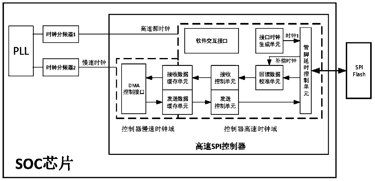
[0037] like figure 1 Shown, a kind of high-speed SPI master mode controller of the present invention, clock signal is provided by PLL, and whole controller is divided into: slow clock domain: comprise DMA control interface, be responsible for the s...


PUM


Abstract

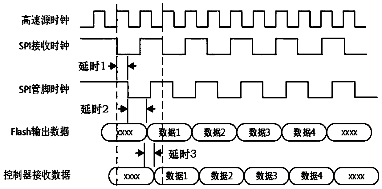
Aiming at the defects of the prior art, the invention relates to a high-speed SPI master mode controller. The structure is improved, so that when the SPI controller works in a low-frequency clock domain, the working frequency of an SPI interface still can be improved to reach the limit of the speed supported by an SPI Flash device. In order to achieve the above goal, the high-speed SPI master modecontroller as the technical scheme is provided. A PLL provides a clock signal; the whole controller is divided into a low-speed clock domain and a high-speed clock domain; and the PLL provides two main clock signals through different clock frequency dividers, wherein the low-speed clock signal is provided for the low-speed clock domain, and the high-speed source clock signal is provided for the high-speed clock domain. Through the technical scheme, the functions of different clock domains are divided by asynchronization of the high-speed SPI controller; the function of high-speed SPI Flash access is realized, so that the read-write time is shortened. Particularly by using application scenarios of SPI FlashBoot, the controller can greatly optimize the start-up time.

Description

technical field [0001] The invention relates to the technical field of electronic circuits, in particular to a high-speed SPI master mode controller. Background technique [0002] SPI (Serial Peripheral Interface), Serial Peripheral Interface, is a synchronous serial interface technology introduced by Motorola. SPI is mainly used between EEPROM, Flash, real-time clock (RTC), digital-to-analog converter (ADC), digital signal processor (DSP) and digital signal decoder. Generally, the maximum clock frequency of the SPI module is 1 / 2 of the system clock frequency. Although the transmission rate of SPI is mainly limited by the ability of the CPU to process SPI data, when communicating with another very high-speed SPI device, the maximum clock frequency of SPI may restrict its transmission rate. The higher the clock, the faster the reading and writing speed can be supported. However, when the SPI clock frequency increases, its controller also needs to work at a higher clock fre...

Claims


Application Information

Patent Timeline
IPC IPC(8): G05B19/042
CPCG05B19/0423G05B2219/25257Y02D10/00G06F13/1689G06F13/30G06F13/4291H03L7/0992
Inventor 兰田田胡胜发
Owner ANYKA (GUANGZHOU) MICROELECTRONICS TECH CO LTD
Learn More