Chip fixing device

A technology for fixing devices and chips, applied in the field of chip manufacturing and processing, can solve the problems of mutual sliding, cumbersome fixing actions, unfavorable use, etc., and achieve the effect of preventing sliding wear

Active Publication Date: 2020-01-10
深圳市晨兴达电子有限公司
View PDF10 Cites 1 Cited by
  • Summary
  • Abstract
  • Description
  • Claims
  • Application Information

AI Technical Summary

Problems solved by technology

[0003] In the process of chip manufacturing and processing, it is usually necessary to fix the chip to facilitate subsequent chip processing, but the existing fixing device is to attach and fix the chip through the relative movement of two fixing pieces, so as to facilitate the overall fixing of the chip, but such fixing The method is not very good to fix the chip. The method of fixing both ends will exert more force on the two ends of the chip, which will easily damage the performance of the chip and the chip, and make the chip not fixed enough. The chip falls, which not only delays the time of the experimenter, but also may cause the ongoing experiment to be forcibly terminated, causing irreparable losses, which is not conducive to people's use; The chip is attached and fixed. During the clamping process of the chip by the two fixing plates on the fixing device, it is easy to make the chip slide with the platform on which the chip is placed, and it is easy to damage the chip; Both use clamping components, but this design makes the fixing action more cumbersome. It is necessary to control the clamping components to clamp or release the chip, and to control the two clamping components to move towards the chip or move away from the chip in the opposite direction.

Method used


Image

  • Chip fixing device
  • Chip fixing device

Examples


Embodiment Construction

[0021] In order to make the object, technical solution and advantages of the present invention clearer, the present invention will be described in further detail below in conjunction with specific embodiments and with reference to the accompanying drawings.

[0022] It should be noted that all expressions using "first" and "second" in the embodiments of the present invention are used to distinguish two entities with the same name but different parameters or parameters that are not the same, see "first" and "second" It is only for the convenience of expression, and should not be construed as a limitation on the embodiments of the present invention, which will not be described one by one in the subsequent embodiments.

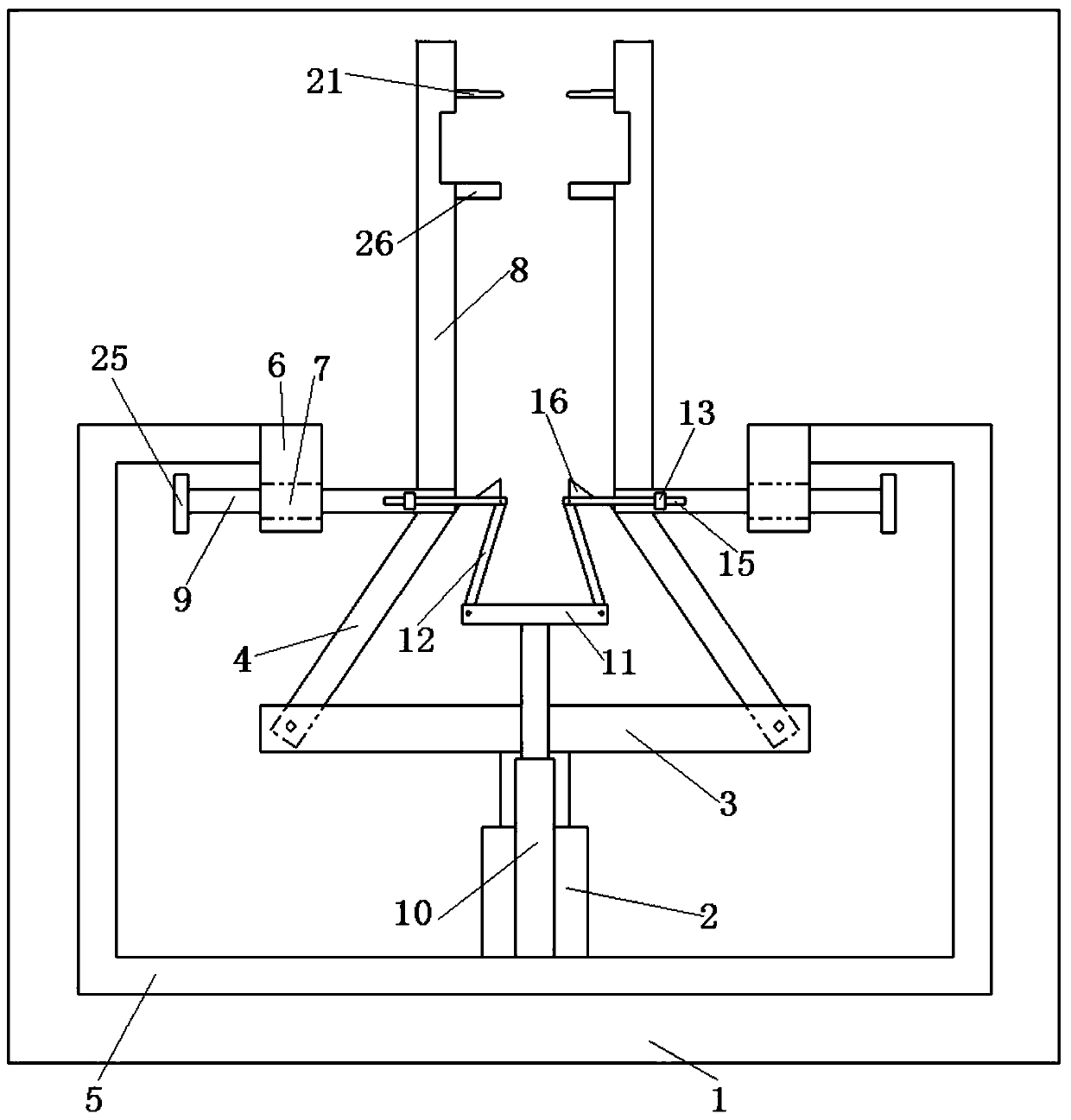
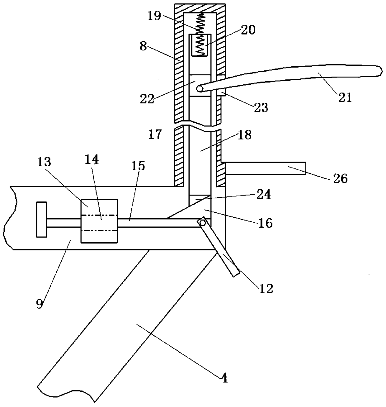
[0023] A chip fixing device, comprising a platform 1, a support frame 5 is arranged on the platform 1, the shape of the support frame 5 is U-shaped, and both ends of the opening of the support frame 5 are transmission-connected with a clamping assembly, The clamp...


PUM


Abstract

The invention discloses a chip fixing device, which comprises a platform, wherein the platform is provided with a supporting frame, the supporting frame is in the shape of a Chinese character 'fang',two ends of an opening of the supporting frame are in transmission connection with clamping assemblies, the clamping assembly comprises a driving structure and two fixing plates arranged at the opening of the supporting frame, the opposite side surfaces of the two fixing plates are provided with clamping grooves, a first distance detection sensor and a second distance detection sensor are respectively arranged in the two clamping grooves, a sliding groove is formed in the platform, a motor is arranged at the end part of the sliding groove, the output end of the motor is connected with a lead screw, the lead screw is in threaded connection with a ball, the upper end of the ball is connected with the supporting frame, the lower end of the ball is connected with a sliding block slidably connected in the sliding groove, and the driving structure drives the two fixing plates to move oppositely or reversely. According to the chip fixing device, the two fixing plates can clamp and fix a chipconveniently, the chip can be effectively prevented from sliding and being abraded on the platform in the clamping process, and the quality of the chip fixing efficiency can be improved conveniently.

Description

technical field [0001] The invention relates to the technical field of chip manufacturing and processing, in particular to a chip fixing device. Background technique [0002] In electronics, a chip is a way to miniaturize circuits (mainly including semiconductor devices, but also passive components, etc.), and is often manufactured on the surface of a semiconductor wafer. [0003] In the process of chip manufacturing and processing, it is usually necessary to fix the chip to facilitate subsequent chip processing, but the existing fixing device is to attach and fix the chip through the relative movement of two fixing pieces, so as to facilitate the overall fixing of the chip, but such fixing The method is not very good to fix the chip. The method of fixing both ends will exert more force on the two ends of the chip, which will easily damage the performance of the chip and the chip, and make the chip not fixed enough. The chip falls, which not only delays the time of the expe...

Claims


Application Information

Patent Timeline
IPC IPC(8): H01L21/687H01L21/67
CPCH01L21/67242H01L21/67259H01L21/68714H01L21/68764
Inventor 孙永武嵇群群
Owner 深圳市晨兴达电子有限公司
Why Eureka
Try Eureka