
Plasma jet velocity monitoring method and device

A plasma and jet velocity technology, applied in the field of plasma jet, can solve the problems of high construction cost of system equipment, complex plasma jet velocity measurement process, etc., to reduce construction cost, improve calculation accuracy and accurate confirmation. Effect

Active Publication Date: 2020-01-10
INST OF MECHANICS - CHINESE ACAD OF SCI
View PDF5 Cites 3 Cited by
  • Summary
  • Abstract
  • Description
  • Claims
  • Application Information

AI Technical Summary

Problems solved by technology

[0004] One of the objectives of the present invention is to provide a method for monitoring the plasma jet velocity, which is used to solve the complicated measurement process of the plasma jet velocity and the high cost of system equipment construction.

Method used


Image

  • Plasma jet velocity monitoring method and device
  • Plasma jet velocity monitoring method and device
  • Plasma jet velocity monitoring method and device

Examples


Embodiment Construction

[0045] The present invention will be described in further detail below in conjunction with the accompanying drawings.

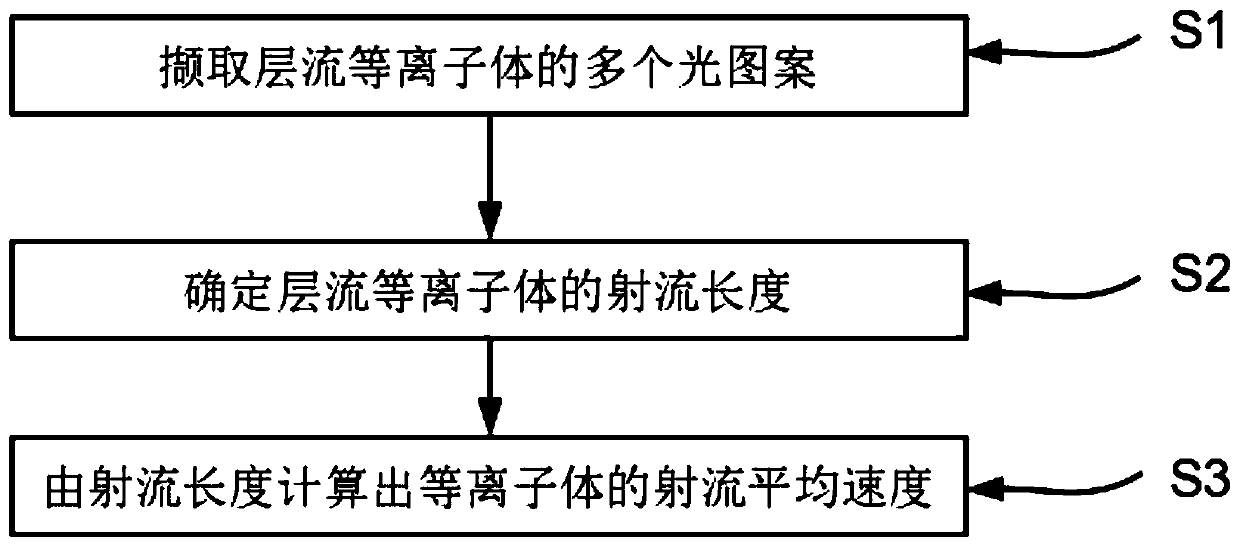
[0046] refer to figure 1 , a method for monitoring plasma jet velocity disclosed in an embodiment of the present invention, comprising:

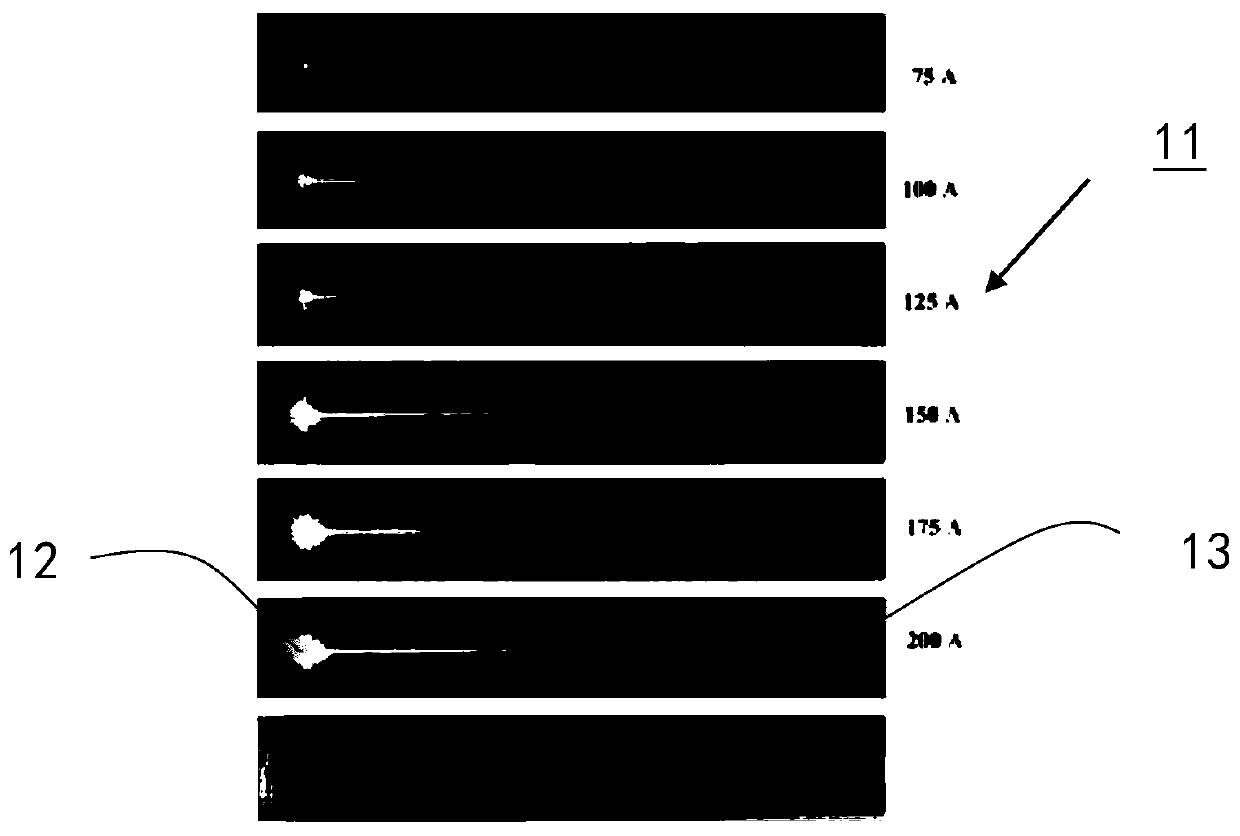
[0047] Step S1: extract a plurality of light patterns of laminar flow plasma, and determine the jet boundary of the plasma jet from the light-emitting boundary of the light pattern based on the positive correlation between the output power and the concentration of the plasma;

[0048] Step S2: determining the jet length of the laminar plasma jet based on the axial jet boundary of the plasma jet from the jet exit to the jet end; and,

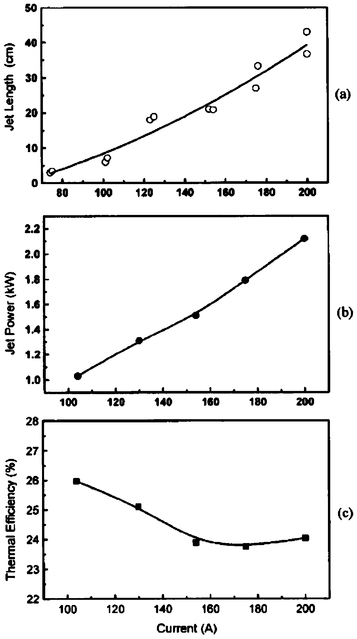
[0049] Step S3: calculating the average jet velocity of the plasma from the jet length of the laminar plasma, including: establishing the relationship between the jet length of the laminar plasma and the arc current under the predetermined different arc current jet velocity. .

[0050] The ...


PUM


Abstract

The invention relates to a plasma jet velocity monitoring method and device. The method comprises the following steps: capturing a plurality of light patterns of laminar plasma, and determining the jet boundary of a plasma jet through the light-emitting boundary of the light patterns based on the positive correlation between the output power and the concentration of the plasma; determining the jetlength of the laminar plasma based on the axial jet boundary of the plasma jet from the jet outlet to the jet end; and calculating the average jet velocity of the plasma according to the jet length of the laminar plasma, and establishing a relation between the jet length of the laminar plasma and the arc current under the condition that different preset arc current jet velocities are kept unchanged. The method has the effects that the plasma jet velocity measurement process is simplified and the construction cost of the measurement system equipment is reduced.

Description

technical field [0001] The invention relates to the technical field of measuring plasma jets, in particular to a monitoring method and equipment for plasma jet velocity. Background technique [0002] At present, plasma spraying is widely used in aerospace, navigation, machinery manufacturing, electronic parts manufacturing and other industrial fields for the formation of coatings for the production of various functional materials required for heat resistance, wear resistance, and corrosion resistance. For example, DC arc plasma is used Plasma spraying methods such as bulk spraying have been the key technology for material spray coating. In DC arc plasma applications, the process material is injected into the plasma laminar jet in the form of particulate powder or gas and is heated and accelerated. Therefore, real-time monitoring of the velocity of the plasma jet is an integral part of process control. Conventional plasma jet velocity measurement process is complex and the ...

Claims


Application Information

Patent Timeline
Patent Type & Authority Applications(China)
IPC IPC(8): H05H1/00
CPCH05H1/0006
Inventor 曹进文黄河激孟显潘文霞
Owner INST OF MECHANICS - CHINESE ACAD OF SCI
Learn More