PLC control cabinet with high dustproof property

A control cabinet, dust-proof technology, applied in the direction of casing/cabinet/drawer parts, electrical equipment casing/cabinet/drawer, electrical components, etc., can solve the problem of poor sealing of rubber strips and lack of dustproofness , Dustproof effect is not good and other problems, to achieve good self-cleaning, anti-twisting force, high dustproof effect

Inactive Publication Date: 2020-01-10
徐州恒诚自动化科技有限公司
View PDF0 Cites 4 Cited by
  • Summary
  • Abstract
  • Description
  • Claims
  • Application Information

AI Technical Summary

Problems solved by technology

[0006] The purpose of the present invention is to provide a high dust-proof PLC control cabinet, to solve the above-mentioned background technology, the heat dissipation window of the PLC control cabinet is only equipped with a dust-proof net cover, which is used to prevent dust from entering the PLC control cabinet through the heat dissipation window , the structure is single, and the dust-proof effect is not good, which is the main factor that causes dust to enter the interior of the cabinet. It does not have good dust-proof performance, and the sealing of the adhesive strips on the cabinet door is not good, which is also the factor that causes dust to enter the interior of the cabinet. One, it needs to be improved and other issues

Method used


Image

  • PLC control cabinet with high dustproof property
  • PLC control cabinet with high dustproof property
  • PLC control cabinet with high dustproof property

Examples


Embodiment Construction

[0023] The following will clearly and completely describe the technical solutions in the embodiments of the present invention with reference to the drawings in the embodiments of the present invention.

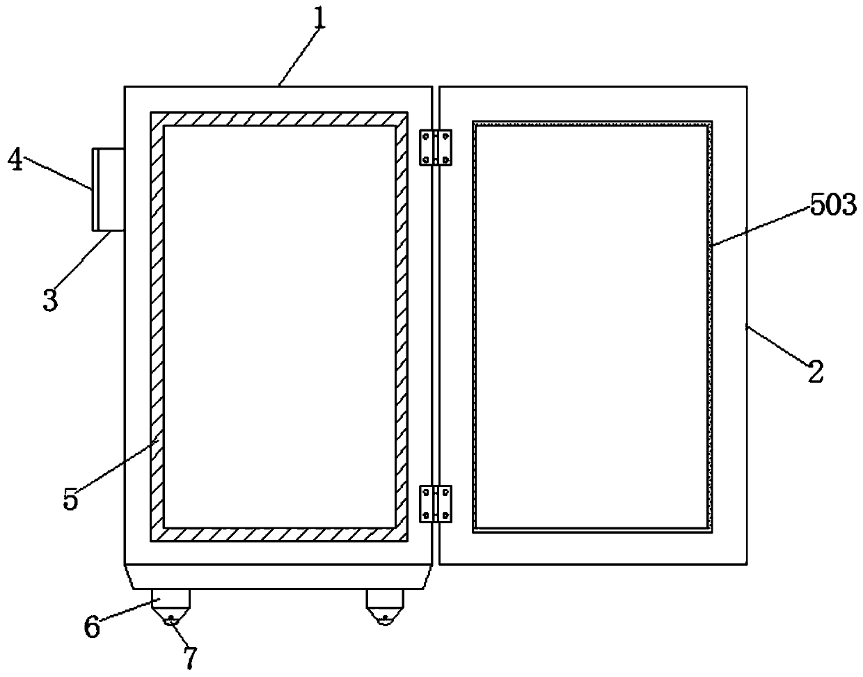
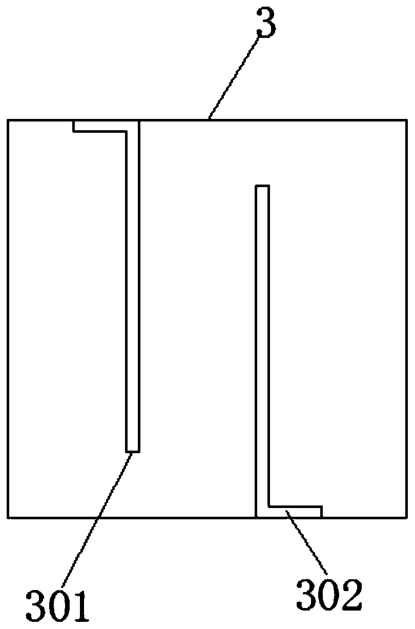
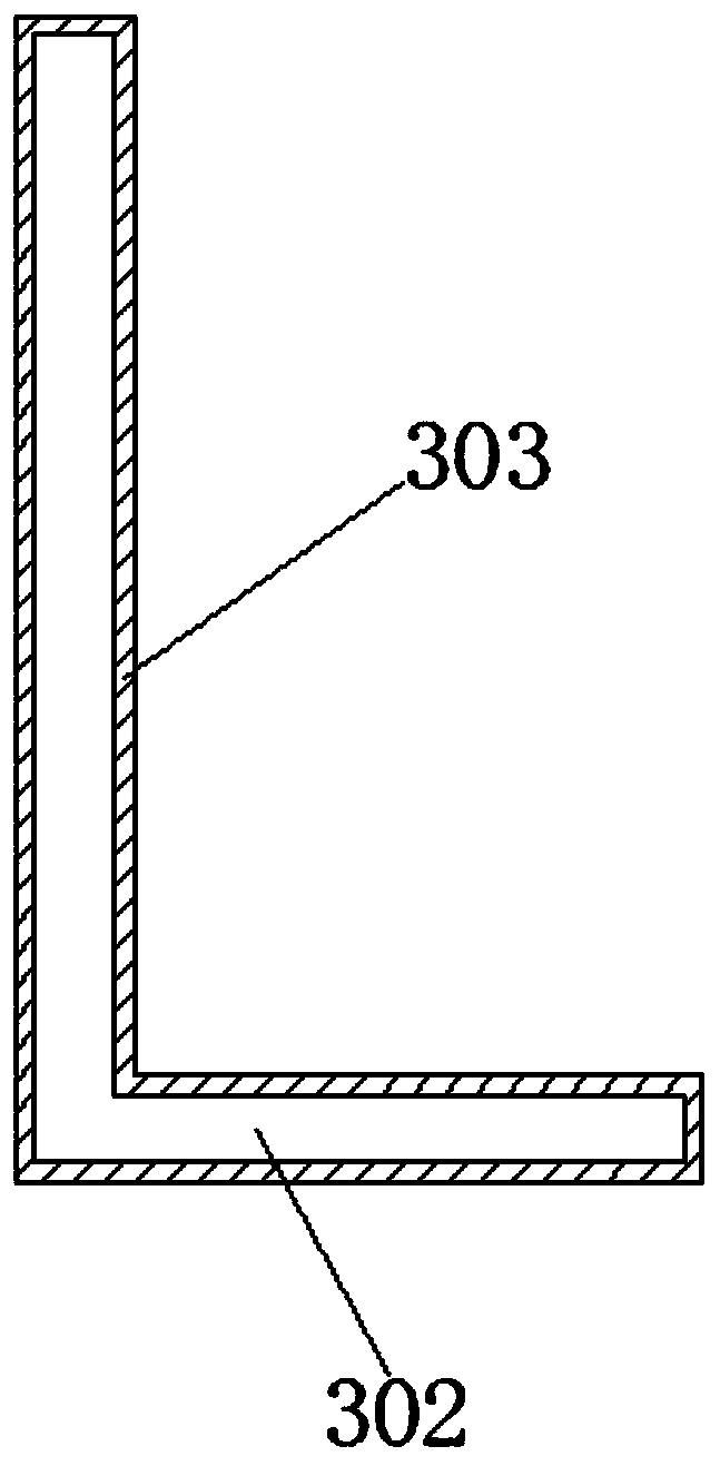
[0024] Such as Figure 1-6 As shown, the present invention provides a technical solution: a high dust-proof PLC control cabinet, including a cabinet body 1 and a cabinet door 2, one side of the cabinet body 1 is connected with a cabinet door 2 through a hinge, and the cabinet body 1. A metal frame 3 is symmetrically welded on the outer walls of both sides, and a No. 1 L-shaped partition 301 is welded in the inner cavity of the metal frame 3. A No. 2 L-shaped partition 302 is welded on one side of the No. 1 L-shaped partition 301 . The surfaces of No. 1 L-shaped partition 301 and No. 2 L-shaped partition 302 are coated with fluorocarbon coating 303, and one end of the metal frame 3 is symmetrically provided with concave holes 304, and one side of the metal frame 3 is detachably...


PUM


Abstract

The invention discloses a PLC control cabinet with high dustproof property. The PLC control cabinet comprises a cabinet body and cabinet door. The cabinet door is connected on one side of the cabinetbody through a hinge. Metal frames are symmetrically welded on the outer walls of the two sides of the cabinet body. A No. 1 L-shape partition plate is welded in the inner cavity of the metal frames.A No. 2 L-shaped partition plate is welded on one side of the No. 1 L-shaped partition plate. A fluorocarbon coating layer is coated on the surface of the No. 1 L-shaped partition plate and the No. 2L-shaped partition plate. The No. 1 L-shaped partition plate and the No. 2 L-shaped partition plate are alternately arranged and there is a gap between one end of the No. 1 L-shaped partition plate and one end of the No. 2 L-shaped partition plate and the inner wall of the metal frames so that an S-shaped gas flow channel is formed in the metal frames. When the cabinet door is closed, an O-shapedsealing strip is embedded in the gap arranged between a No.1 silica gel strip and a No.2 silica gel strip, and the O-shaped sealing strip is respectively attached to the No.1 silica gel strip and theNo.2 silica gel strip so that all irregular surfaces, holes and gaps of joints can be fully filled, and the sealing effect at the junction of the cabinet door and the cabinet body is effectively improved.

Description

technical field [0001] The invention relates to the technical field of PLC control cabinets, in particular to a high dust-proof PLC control cabinet. Background technique [0002] The PLC control cabinet has protection functions such as overload, short circuit, and phase loss protection. It has compact structure, stable operation and complete functions. It can be combined according to the size of the actual control scale, which can not only realize the automatic control of a single cabinet, but also realize the distribution (DCS) control system composed of multiple cabinets through industrial Ethernet or industrial field bus network. [0003] However, the existing PLC control cabinet mainly has the following disadvantages: [0004] 1. The heat dissipation window used for heat dissipation of the PLC control cabinet is only installed with a dust-proof net cover to prevent dust from entering the interior of the PLC control cabinet through the heat dissipation window. The struc...

Claims


Application Information

Patent Timeline
Patent Type & Authority Applications(China)
IPC IPC(8): H05K5/02H05K5/06
CPCH05K5/0213H05K5/0217H05K5/0234H05K5/061
Inventor 吴云
Owner 徐州恒诚自动化科技有限公司
Why Eureka
Try Eureka