Solid-state solar paint

A coating layer, conductive coating technology, applied in the field of solid-state solar coatings, to achieve the effect of reducing capital expenditure requirements, small manufacturing and transportation costs, and reducing import and export taxes or duties

Inactive Publication Date: 2020-01-10
GOOGLE LLC
View PDF2 Cites 0 Cited by
  • Summary
  • Abstract
  • Description
  • Claims
  • Application Information

AI Technical Summary

Problems solved by technology

In general, commercial solar cell manufacturing requires highly specialized equipment, limiting manufactured solar cells to geographic locations with access to sophisticated manufacturing equipment and / or specialized shipping and installation capabilities

Method used


Image

  • Solid-state solar paint
  • Solid-state solar paint
  • Solid-state solar paint

Examples


Embodiment Construction

[0027] overview

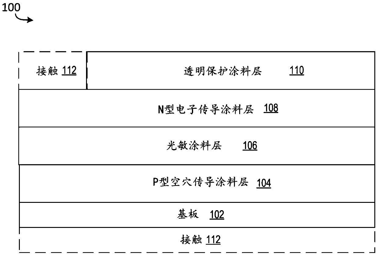
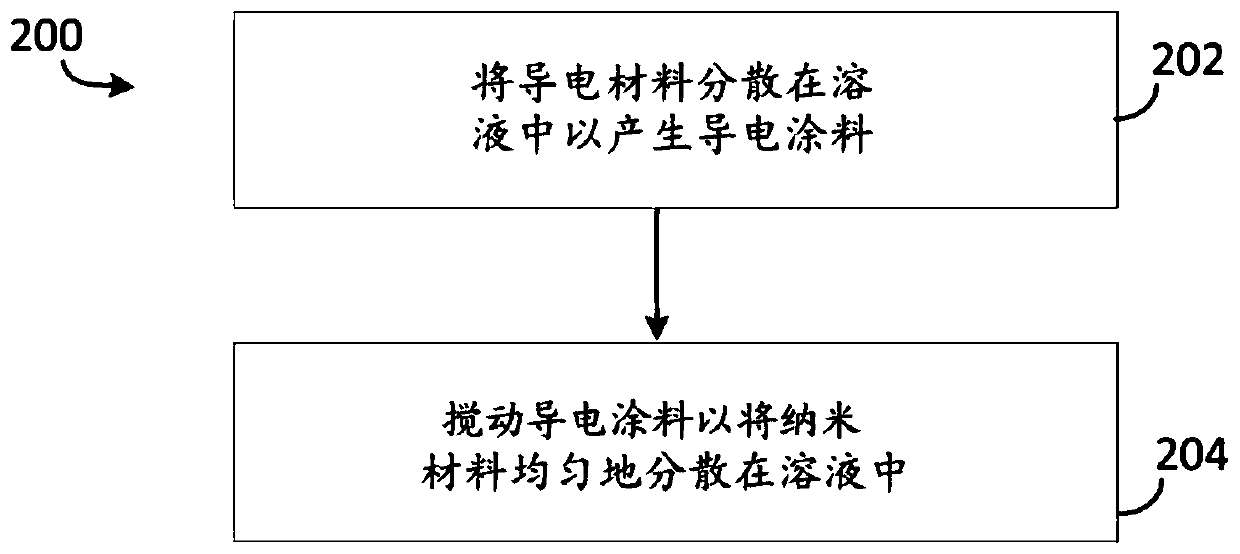
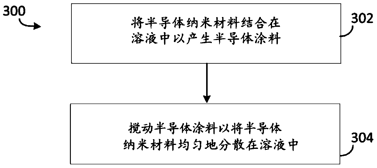
[0028] Devices, systems and methods for producing solar paint and solar paint circuits are described below. Paint circuits (eg, solar paint circuits) are created by applying conductive paint (eg, solar paint circuits) layer by layer to the surface of a substrate. The substrate can be, for example, a piece of wood, brick, stucco, stone, metal surface, or other surface to which a paint can be applied. The solar paint layer can be manually applied to the substrate using an aerosol dispenser or other aerosolized spray tool.

[0029] Although the terms "solar paint circuit" and "solar paint" are used in the context of describing particular embodiments of the inventive subject matter, this is not meant to be limiting. Other paint circuits that do not incorporate solar energy (such as batteries, LEDs, antennas, or other circuit elements) can be implemented, as well as paint layers that do not directly participate in forming a solar-incorporating circuit.

[003...


PUM

PropertyMeasurementUnit
diameteraaaaaaaaaa

Abstract

Methods and devices for forming painted circuits using multiple layers of electrically conductive paint. In one aspect, a painted circuit includes a substrate (102) and one or more paint layers (104,106, 108) applied to the substrate where the one or more paint layers each form an electrical component of the painted circuit, and where the one or more paint layers includes a p-type hole conductingpaint layer (104) applied to the substrate (102), a photosensitized paint layer (106) applied to the p-type hole conducing paint layer (104), an n-type electron conducting paint layer (108) applied to the photosensitized paint layer (106), and a transparent protective paint layer (110) applied to the n-type electron conducting paint layer (108).

Description

[0001] Cross References to Related Applications [0002] This application claims the benefit of U.S. Patent Application No. 62 / 558,579, filed September 14, 2017, entitled "Paint Circuits," and U.S. Patent Application No. 15 / 5, filed April 16, 2018, entitled "Solid State Solar Coatings." 954,283 interests. The disclosure of the aforementioned application is hereby incorporated by reference in its entirety for all purposes. Background technique [0003] Conventional solar cells use a substrate with a highly regular crystal structure, eg, crystalline silicon. Newer technologies include thin-film amorphous solar cells to build up discrete layers of individual materials with highly regular and predictable chemical structures. In general, commercial solar cell manufacturing requires highly specialized equipment, which limits the solar cells manufactured to geographic locations where sophisticated manufacturing equipment and / or specialized shipping and installation capabilities are...

Claims


Application Information

Patent Timeline
Patent Type & Authority Applications(China)
IPC IPC(8): H01G9/20
CPCH01G9/2068H01G9/2095H01G9/2059H01G9/2031C09D5/22H01L28/20Y02E10/542Y02E10/549Y02E60/10Y02P70/50H10K65/00H10K39/10H10K59/60H10K71/13H10K71/40H01G9/0036H01G9/204H01L31/053H01L31/02021H01L31/125H03K2217/96019F21K9/64H10K71/15H10K19/10H10K30/30H10K30/80H10K30/81H10K30/88H10K50/11H10K50/135H10K59/00H10K85/141H10K85/1135H10K10/20H10K85/311H10K2101/10C09D7/65C09D7/61C08K3/16C08K3/22C08K2003/2241C09D5/24C09D5/32C09D133/26C09D157/06C09D201/00F21S9/037H01G9/0029H01G9/2013H01G9/2022H01M10/465
Inventor K.卡斯迈H.K.维斯塔尔
Owner GOOGLE LLC
Why Eureka
Try Eureka