
Clamping mechanism for robot-assisted lower limb fracture reduction operation

A robot-assisted and clamping mechanism technology, applied in the field of robots, can solve the problems of inconvenient operation, unstable fixation of broken bones, affecting the safety and accuracy of fracture reduction surgery, and achieves the effect of convenient operation and good versatility

Active Publication Date: 2020-01-14
SHANGHAI UNIV
View PDF19 Cites 6 Cited by
  • Summary
  • Abstract
  • Description
  • Claims
  • Application Information

AI Technical Summary

Problems solved by technology

[0002]With the development of medical technology, people have gradually increased the requirements for the safety and convenience of fracture reduction surgery, and robot-assisted fracture reduction surgery has gradually replaced traditional surgery. The doctor manually resets. At present, the lower limb fracture reduction robot mainly uses a parallel reduction robot. The fracture fixation mechanism of the existing parallel reduction robot has a fixed blind spot near the femoral head. Directly affect the safety and accuracy of fracture reduction surgery
[0003]On the other hand, in order to improve the safety of surgery, people have introduced sensorless external force estimation and collision detection technology into parallel fracture reduction robots. There is a lack of a reset force test module in the system, and it is impossible to obtain the change law of the end reset force and the driving force of the linear electric cylinder during the fracture reduction process.

Method used


Image

  • Clamping mechanism for robot-assisted lower limb fracture reduction operation
  • Clamping mechanism for robot-assisted lower limb fracture reduction operation
  • Clamping mechanism for robot-assisted lower limb fracture reduction operation

Examples


Embodiment Construction

[0020] The present invention will be further described below with reference to the embodiments and the accompanying drawings.

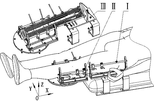
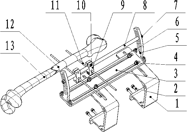
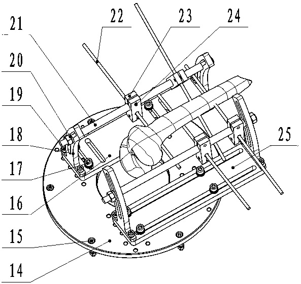
[0021] like figure 1 As shown, a clamping mechanism for robot-assisted lower extremity fracture reduction surgery is composed of a proximal fracture fixing mechanism module I, a distal fracture clamping mechanism module II, and a reduction force testing module III. The proximal fracture fixing module is composed of The bracket 1 of I is fixed on the frame of the operating bed through the first bolt 2, the proximal fracture fixing module I fixes the proximal fracture 12 through the first bone pin 11, and the connecting plate 14 of the distal fracture clamping module II is connected to the parallel reduction robot. The moving platform is connected by the third bolt 15, the fracture distal end clamping module II clamps the fracture distal end 13 through the second bone pin 22, and the distal muscle bundle fixing plate 26 of the reduction force test modul...


PUM


Abstract

The invention relates to a clamping mechanism for a robot-assisted lower limb fracture reduction operation. The clamping mechanism is composed of a fracture near-end fixing module, a fracture far-endclamping module and a reduction force testing module. The fracture near-end fixing module is installed on an operating bed. The fracture near-end fixing module is used for fixing a fracture near end through a bone needle; the fracture far-end clamping module is connected with a movable platform of a parallel reduction robot; the fracture far-end clamping module clamps the fracture far end throughthe bone needle, a far-end muscle bundle fixing plate of the reduction force testing module is installed on an arc support of the fracture far-end clamping module, and a force sensor installation baseof the reduction force testing module is fixed to a support of the fracture near-end fixing module. The clamping mechanism can achieve the fixing of the fracture near end of the lower limb of a patient, the clamping of the fracture far end and the precise reduction operation, can test the change rule between the reduction force and the driving force of a linear electric cylinder in the fracture reduction process, and can be used for the external force estimation and collision detection in the parallel reduction robot operation reduction process.

Description

technical field [0001] The invention belongs to the technical field of robots, and relates to a clamping mechanism used for robot-assisted lower limb fracture reduction surgery. Background technique [0002] With the development of medical technology, people's requirements for the safety of fracture reduction surgery and the convenience of surgical operations are gradually increasing. Robot-assisted fracture reduction surgery gradually replaces the traditional manual reduction by surgeons. At present, lower limb fracture reduction robots mainly use parallel reduction robots. The fracture fixation mechanism of the existing parallel reduction robot has a fixation blind spot near the femoral head, which is inconvenient to operate and the fracture fixation is not firm during the fracture fixation process. These problems directly affect the safety and accuracy of fracture reduction surgery. [0003] On the other hand, in order to improve the safety of the operation, people introd...

Claims


Application Information

Patent Timeline
Patent Type & Authority Applications(China)
IPC IPC(8): A61B17/66A61B90/00A61B90/14
CPCA61B17/66A61B90/06A61B90/14A61B2017/564
Inventor 雷静桃郑功亮
Owner SHANGHAI UNIV
Learn More