

Recognition device for team fighting gyro and team fighting gyro
A technology for identifying devices and gyroscopes, which is applied in the field of team battle gyroscopes, can solve the problems of complex operation and high cost of electronic identification, and achieve the effect of high winning rate
- Summary
- Abstract
- Description
- Claims
- Application Information
AI Technical Summary
Problems solved by technology
Method used
Image

Examples
Embodiment 1
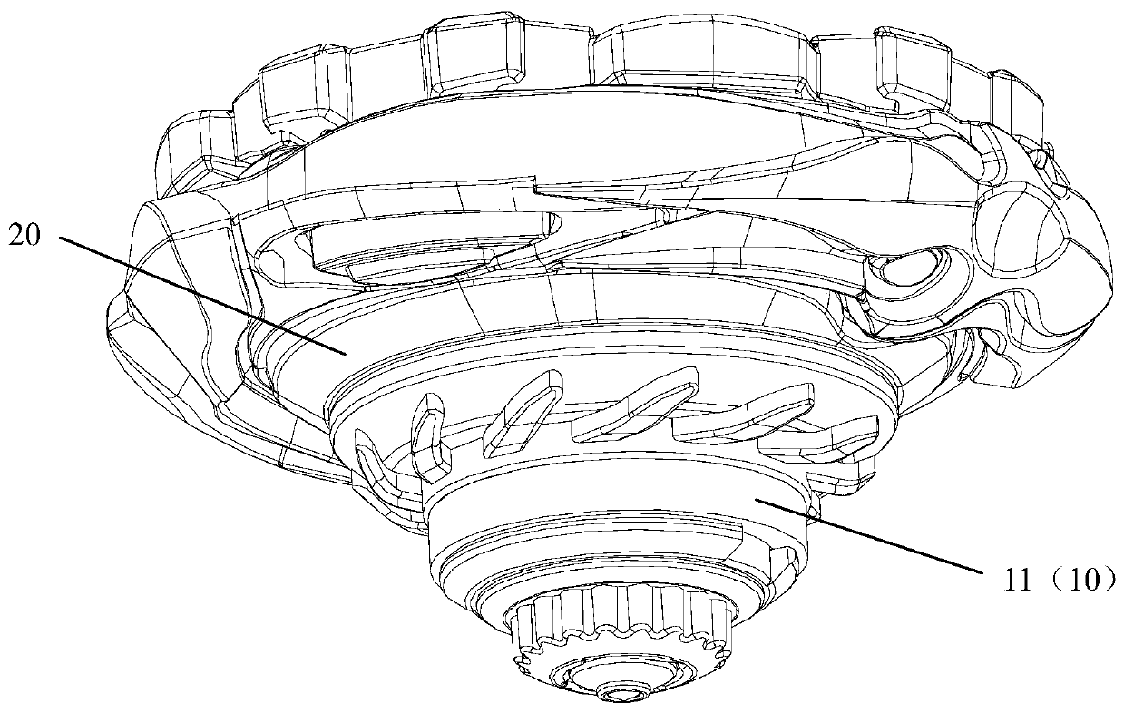
[0072] Such as Figure 1-3 As shown, the team battle top includes a top body 20 and an identification device 10 . The identification device 10 includes a magnetic unit 11. The magnetic field range of the magnetic unit 11 is larger than the lateral edge of the team battle top. The magnetic unit 11 is used to form the team battle top and adjacent tops with the same magnetic poles into the same team. Neighboring spinning tops with opposite magnetic properties or without magnetic properties form a battle state.
[0073] In Embodiment 1, the identification device 10 is set outside the gyroscope body 20, the magnet of the magnetic unit 11 is circular, and the magnetic field range of the magnetic unit 11 set outside is larger, and it is easier to generate damage to adjacent gyroscopes. influences.
[0074] The magnetic pole directions of the annular magnetic units 11 of the same team are all arranged laterally, and the magnetic poles are the same.
[0075] Optionally, the magnet c...
Embodiment 2
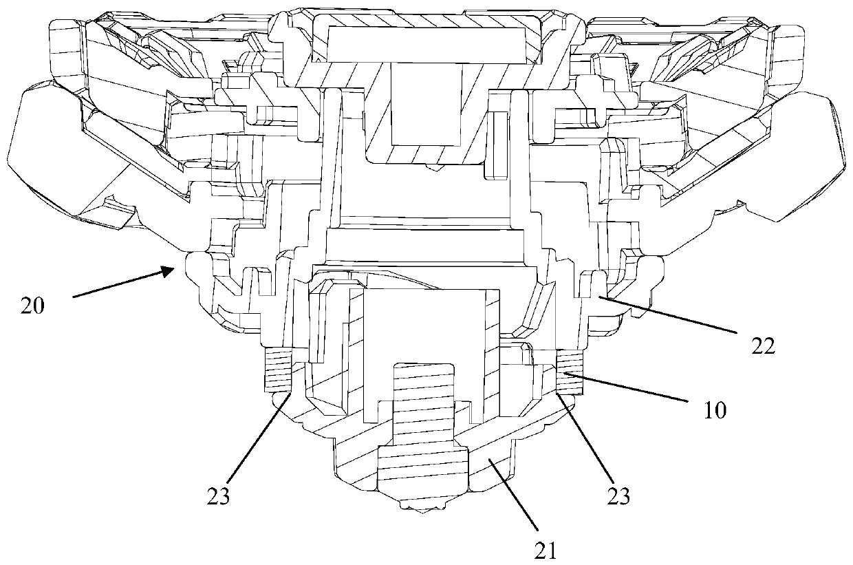
[0083] Such as Figure 4-5 As shown, the identification device 10 is installed inside the middle of the gyroscope body 20 .
[0084] Specifically, an embedding cavity 24 (which may be equivalent to a connecting component) is formed between the upper gyro body 22 of the gyro body 20 and the tip 21. The embedding cavity 24 is formed inside the gyro body 20, and the magnetic unit 11 is embedded in the embedding. The cavity 24 is located inside the top body 20, and the magnetic unit 11 cannot be seen from the outside.
[0085] For the installation stability of the magnetic unit 11, and to prevent the magnetic unit 11 from being damaged due to the impact force transmitted to the magnetic unit 11 when the gyroscope body 20 is hit, the connecting assembly can also be designed as an independent piece for installing the magnetic unit 11, for example : The connection assembly is a housing with one end open for the magnetic unit 11 to be loaded into. The periphery of the housing is made...
Embodiment 3
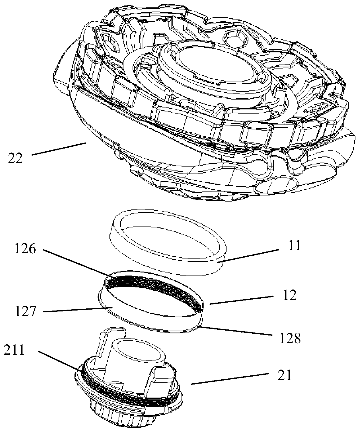
[0092] Such as Figure 6-7 As shown, the identification device 10 is also sheathed on the outside of the gyroscope body 20 .
[0093] Among them such as Figure 6 As shown, the magnetic unit 11 is a ring magnet, and the inner edge wall of the upper end surface of the ring magnet extends radially toward the center of the circle with an overlapping edge, through which the overlapping edge is overlapped on the top of the top seat 27, and then passed through the top The tip seat 27 is connected and fixed to the upper part of the top body 20 , so as to realize the fixing of the magnetic unit 11 on the top body 20 .
[0094] another example Figure 7 As shown, the identification device 10 may also include a connection assembly 12, the connection assembly 12 includes an inner ring wall 121, an outer ring wall 122 located at the periphery of the inner ring wall 121 and arranged at intervals, and an upper edge of the inner ring wall 121 for The screwing card edge 123 that is rotatab...
PUM
 Abstract
Description
Claims
Application Information