Supporting construction technology for deep foundation pit nearby road on complicated geological conditions
A technology of complex geological conditions and deep foundation pit support, applied in infrastructure engineering, sheet pile walls, excavation, etc., can solve problems such as difficult support for deep foundation pits, high construction costs, and potential safety hazards, and eliminates the need for Potential safety hazards, reduced construction costs, and the effect of reducing the amount of backfill
- Summary
- Abstract
- Description
- Claims
- Application Information
AI Technical Summary
Problems solved by technology
Method used
Image

Examples
Embodiment
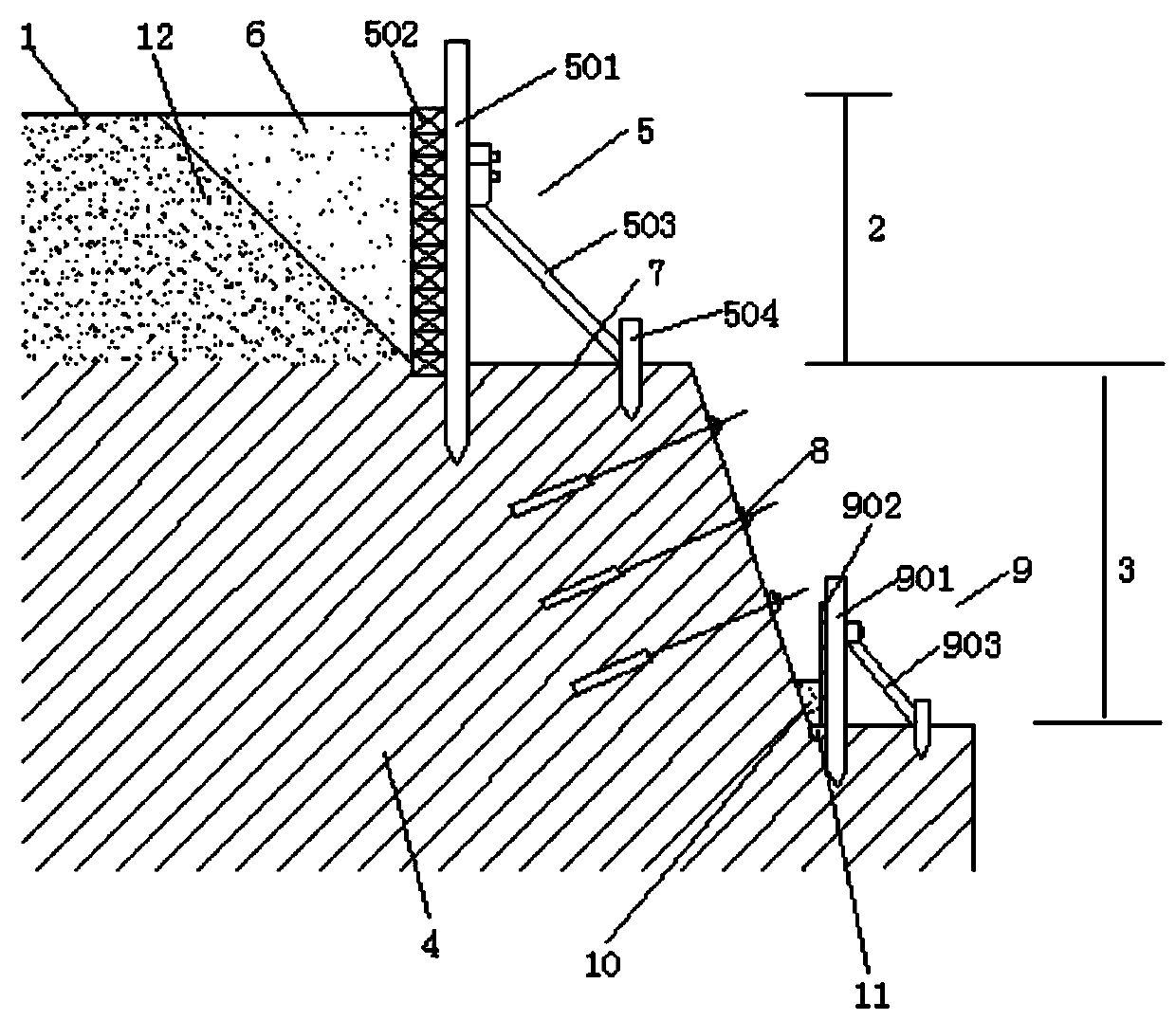
[0021] Take the Chengdu-Chuanzhusi section CLZF-2 bid project undertaken by the applicant as an example. The project includes a total of 5 station buildings including Maoxian Station, Zhenjiangguan Station, Songpan Station, Chuanzhusi Station and Huangshengguan Station , among them, during the construction of Huangshengguan and Chuanzhusi station building projects, the temporary site on site was relatively narrow, the excavation line of the foundation pit was about 50cm away from the temporary road on site, and the depth of the foundation pit was more than 5m. Very high soil layer, the lower part is a hard and compact rock layer, and the traditional support structure cannot be applied. In order to solve this problem, the present invention, such as figure 1 Shown, the deep foundation pit supporting construction technology that the present invention adopts comprises the following steps:
[0022] Step 1. Excavate the foundation pit beside the road subgrade 1 until the bottom of t...
PUM
 Abstract
Description
Claims
Application Information
 - R&D
- Intellectual Property
- Life Sciences
- Materials
- Tech Scout
- Unparalleled Data Quality
- Higher Quality Content
- 60% Fewer Hallucinations
Browse by: Latest US Patents, China's latest patents, Technical Efficacy Thesaurus, Application Domain, Technology Topic, Popular Technical Reports.
© 2025 PatSnap. All rights reserved.Legal|Privacy policy|Modern Slavery Act Transparency Statement|Sitemap|About US| Contact US: help@patsnap.com