Compressor and refrigeration device

A technology for a compressor and a driving motor, applied in the field of compressors, can solve the problems of poor reliability of the upper bearing, poor reliability of the compressor, poor stiffness of the crankshaft, etc., so as to improve the operation stability and reliability, improve the reliability and use Longevity and wear reduction effect

Inactive Publication Date: 2020-01-14
ANHUI MEIZHI PRECISION MFG
View PDF6 Cites 2 Cited by
  • Summary
  • Abstract
  • Description
  • Claims
  • Application Information

AI Technical Summary

Problems solved by technology

[0003] With the development trend of high efficiency, miniaturization and high speed of compressors, and in order to improve mechanical efficiency, the crankshaft shaft diameter is often designed to be smaller, and the crankshaft stiffness is poorer.
Since the centrifugal force is directly proportional to the quadratic of the rotational speed, for high rotational speed compressors, the crankshaft will be seriously deformed under the action of the centrifugal force and bending moment generated by the balance weight on the rotor, and wear with the upper bearing, making the upper bearing Poor reliability, which in turn makes the reliability of the compressor worse

Method used


Image

  • Compressor and refrigeration device
  • Compressor and refrigeration device

Examples


Embodiment 1

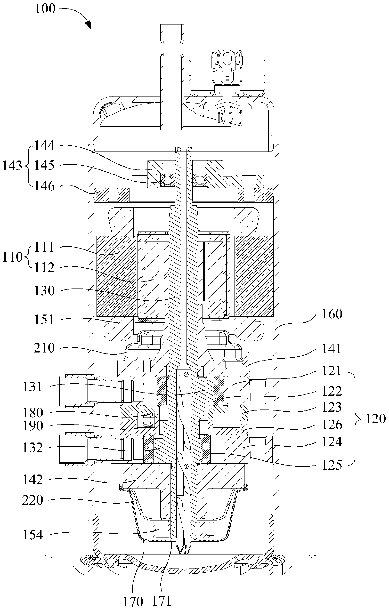
[0045] Such as figure 1 and figure 2 As shown, the first aspect embodiment of the present invention proposes a compressor 100 with a maximum speed greater than or equal to 150rps (revolution / second), including a housing 160, a drive motor 110, a compression assembly 120, a crankshaft 130, a bearing system and a balance system. Wherein, the bottom of housing 160 is configured as an oil pool; drive motor 110 includes stator 111 and rotor 112; compression assembly 120 includes a first cylinder 121, a first piston 122, a second cylinder 124, a second piston 125, and a first cylinder 121 and the partition plate of the second cylinder 124, the first piston 122 is arranged in the first cylinder 121, the second piston 125 is arranged in the second cylinder 124; the crankshaft 130 has a first eccentric part 131 and a second eccentric part 132, the second An eccentric part 131 and a second eccentric part 132 are relatively distributed around the rotation centerline of the crankshaft ...

Embodiment 2

[0050] Different from Embodiment 1, the rotation centerlines of the first eccentric portion 131 and the second eccentric portion 132 around the crankshaft 130 are 90° apart. That is, the projections of the first eccentric portion 131 and the second eccentric portion 132 on a cross section of the crankshaft 130 differ by 90° in central angle.

[0051] Of course, it is also possible to have a difference of 60° or 120° around the rotation centerline of the crankshaft 130 and so on.

Embodiment 3

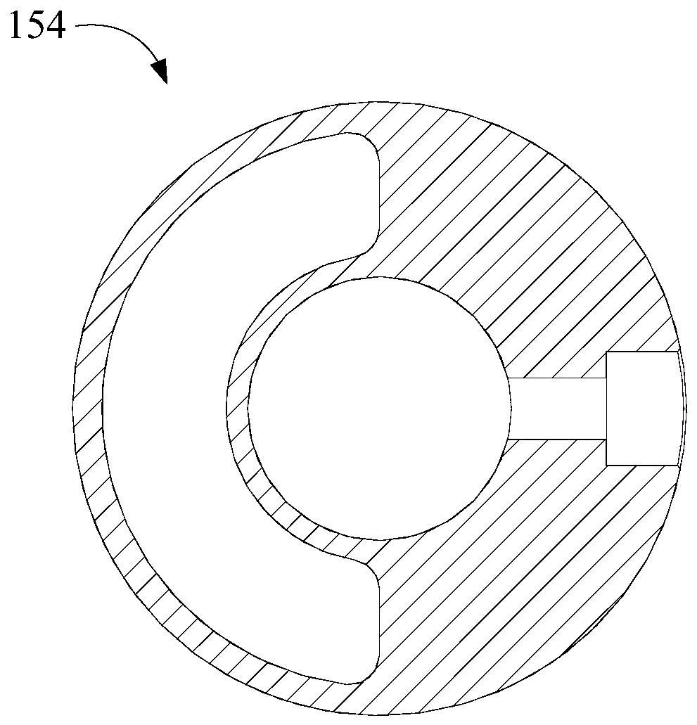
[0053] On the basis of the first or second embodiment above, it is further set that the center of mass of the rotor balance weight 151 and the first eccentric portion 131 are relatively distributed around the center line of rotation of the crankshaft 130; They are relatively distributed around the rotation centerline of the crankshaft 130 . So that no matter how the first eccentric part 131 and the second eccentric part 132 are distributed, the unbalanced force and moment brought by the eccentric movement of the first eccentric part 131 and the first piston 122 can be offset by the rotor balance weight 151, and The unbalanced force and moment caused by the eccentric movement of the second eccentric portion 132 and the second piston 125 is offset by the crankshaft balance weight 154 . Since the first eccentric part 131 and the second eccentric part 132 do not need to be independently balanced by the rotor balancing weight 151, the weight of the rotor balancing weight 151 can be...


PUM


Abstract

The invention provides a compressor and a refrigeration device. The compressor comprises a housing, a stator, a rotor, a first air cylinder, a first piston, a second air cylinder, a second piston, a crankshaft, a bearing system, a balance system and an insulation hood, wherein the first piston is arranged in the first air cylinder; the second piston is arranged in the second air cylinder; the crankshaft is provided with a first eccentric part and a second eccentric part; the first piston is arranged on the first eccentric part in a sleeving manner; the second piston is arranged on the second eccentric part in a sleeving manner; the crankshaft penetrates through the rotor and a compression component; the bearing system comprises a first bearing, a second bearing and an auxiliary bearing; the first bearing is arranged on one side, close to a driving motor, of the first air cylinder; the second bearing is arranged on one side, far from the driving motor, of the second bearing; the auxiliary bearing is arranged on the crankshaft and positioned on one side, far from the compression component, of the driving motor; the balance system comprises a rotor balance block and a crankshaft balance block; the rotor balance block is arranged on the rotor; the crankshaft balance block is arranged on the crankshaft and positioned on one side, far from the first bearing, of the second bearing; and a part of the isolation hood surrounds the crankshaft balance block. The high-speed operation reliability of the compressor is improved.

Description

technical field [0001] The invention belongs to the technical field of compressors, and in particular relates to a compressor and a refrigeration device. Background technique [0002] In the rolling rotor compressor, in the axial direction of the crankshaft, there are rotor, upper bearing, cylinder and lower bearing in sequence. The crankshaft with eccentric part rotates under the drive of the rotor, and the piston sleeved on the eccentric part performs eccentric motion compression in the cylinder. The gas does work. Due to the existence of the eccentric part and the eccentric movement of the piston, it is necessary to set up balance weights on the upper and lower sides of the rotor to offset the unbalanced force and moment. The centrifugal force and bending moment generated by the balance weight on the upper side of the rotor and the balance weight on the lower side of the rotor will act on the crankshaft, and the resulting bending deformation of the crankshaft is mainly s...

Claims


Application Information

Patent Timeline
Patent Type & Authority Applications(China)
IPC IPC(8): F04C29/00F04C29/02F04C29/12F04C23/00
CPCF04C23/001F04C29/00F04C29/0021F04C29/02F04C29/124
Inventor 罗承卓谭琴朱晓涵
Owner ANHUI MEIZHI PRECISION MFG
Why Eureka
Try Eureka